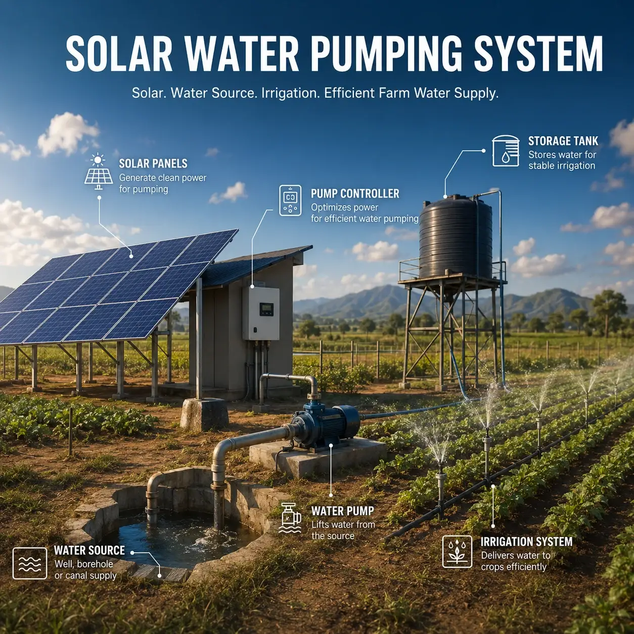
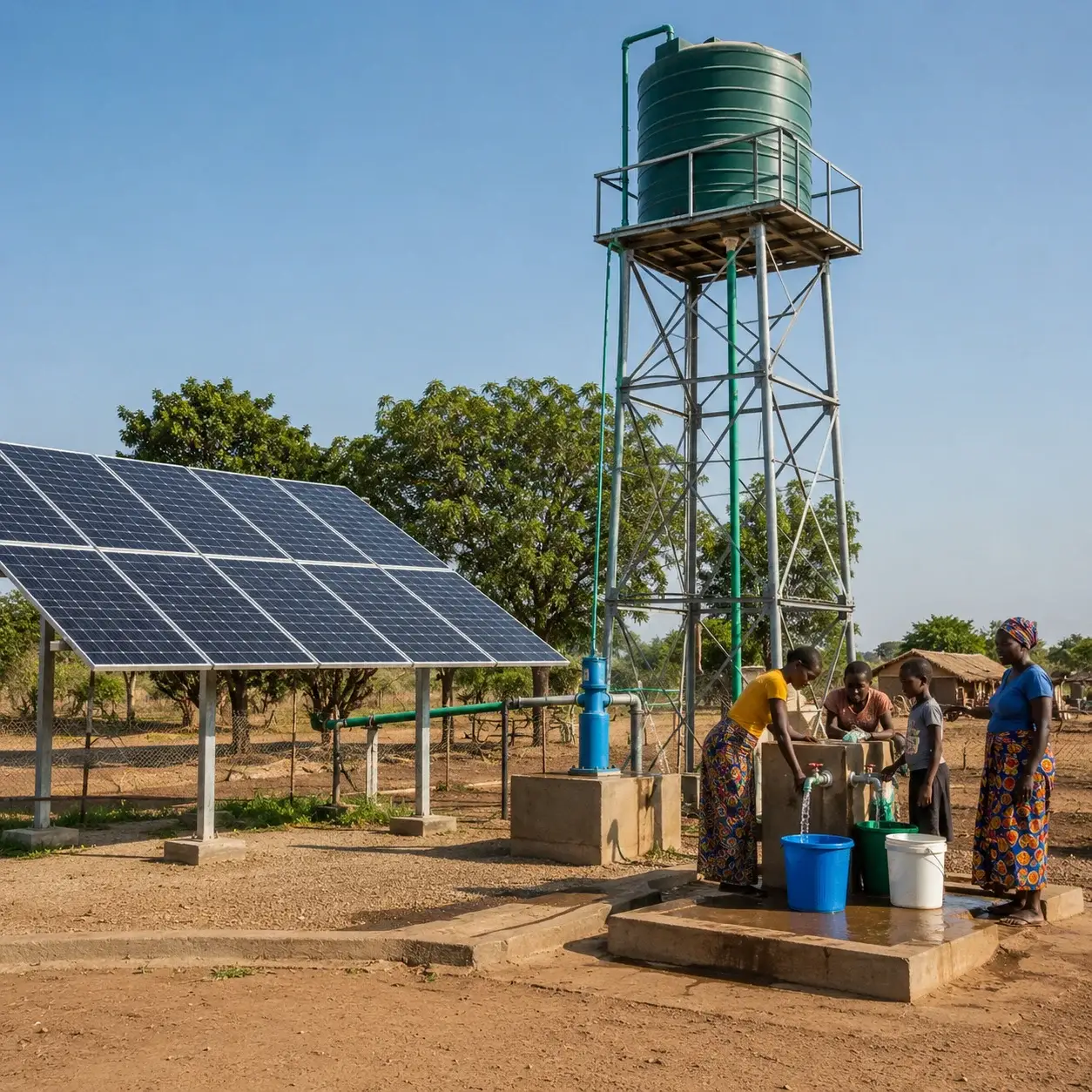
Your Trusted Solar Water Pumping SystemSupplier and Integration Partner
Need a solar pumping system that truly matches your project? We configure the panels, pump inverter, mounting, protection and backup options around your required flow, total head and operating hours—helping you quote faster, avoid compatibility risks and deliver reliable irrigation, borehole and water-supply projects with confidence.

Solar Water Pumping System
At Mars Solar, we know you are not simply looking for a pump and a few solar panels. You need a system that can deliver the required water volume under the actual conditions of your project. That means matching the solar array, pump inverter, pump power, total dynamic head, pipe distance, operating hours, and protection equipment from the beginning. When these factors are calculated correctly, you avoid undersized systems, unstable water output, and unnecessary installation delays.
We support four practical configurations: DC Solar Water Pumping Systems for smaller off-grid applications, Single-Phase AC Systems for farms and light commercial projects, Three-Phase AC Systems for deep wells and higher-flow requirements, and Hybrid Solar Systems with Grid or Generator Backup for projects that require longer and more reliable pumping hours. We select the configuration around your water demand and site conditions rather than forcing your project into a fixed catalogue package.
Whether you are preparing an EPC quotation, expanding your distribution range, converting an existing pump to solar, or delivering an irrigation project, you have come to the right place. We help you organize the panels, pump inverter, mounting, cables, protection, sensors, optional pump, and technical documents into one supply-ready solution—so you can quote faster, reduce compatibility risks, and move the project forward with confidence.

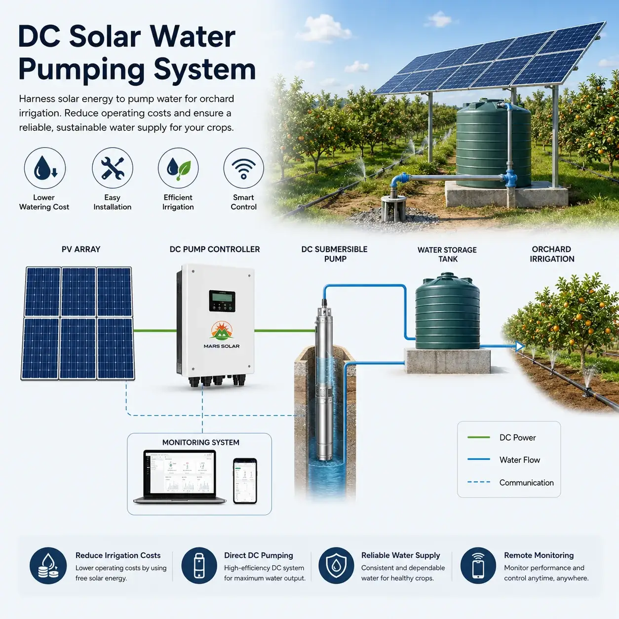
DC Solar Water Pumping System
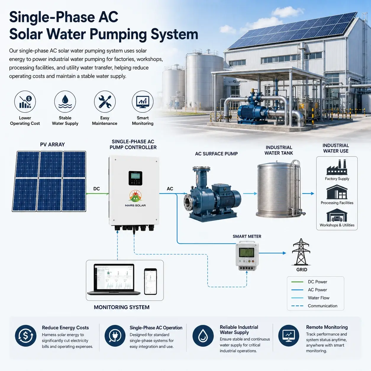
Single-Phase AC Solar Water Pumping System
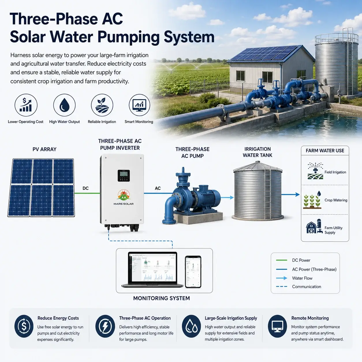
Three-Phase AC Solar Water Pumping System
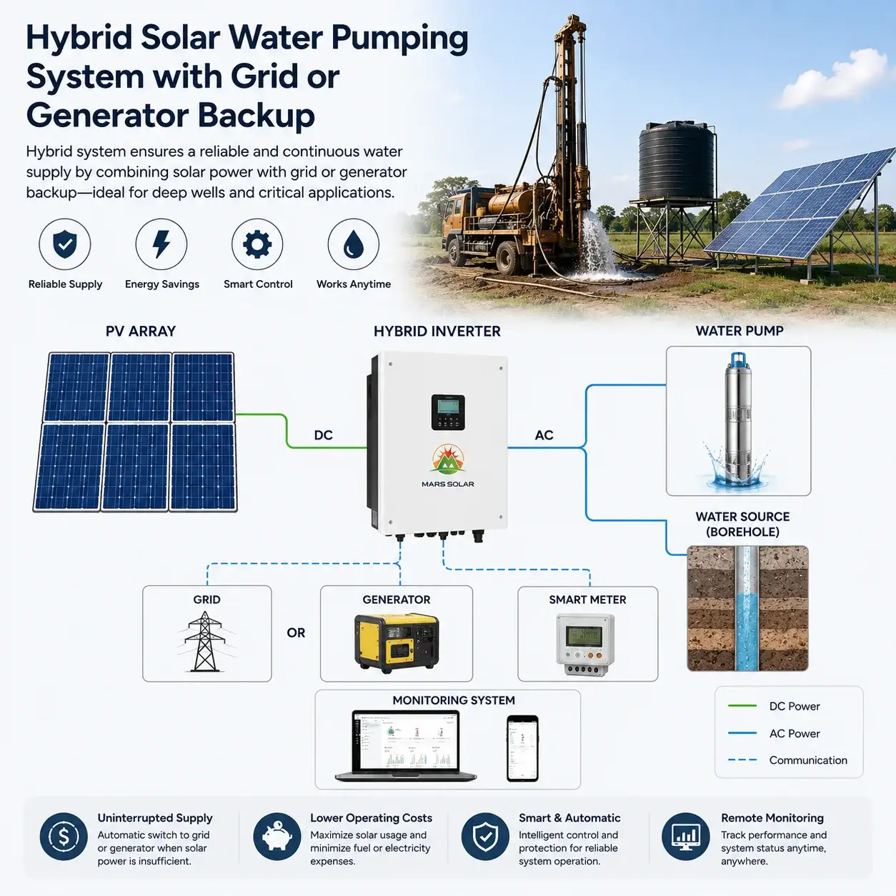
Hybrid Solar Water Pumping System with Grid or Generator Backup
Build a Solar Water Pumping System Around Your Real Project
If you already have an irrigation project, a borehole, an installation team, a local sales channel, or a customer waiting for a quotation, you have come to the right team. We understand that you are not looking for another catalogue filled with pumps and solar panels. You need a partner who can understand the project quickly, match the correct equipment, and turn the water requirement into a complete, supply-ready solar pumping system.
A solar water pumping project cannot be defined only by pump power. Two systems using the same 5.5 kW pump may require completely different solar arrays, pump inverters, cable sizes, protection devices, and operating strategies. Before recommending a configuration, we review the required flow rate, total dynamic head, water-source depth, pipe distance, pump voltage, daily operating hours, local solar conditions, and available backup power. This helps us avoid undersized systems, unstable water output, and preventable installation problems.
Our Four Core Solar Water Pumping System Configurations
DC Solar Water Pumping System: This configuration is suitable for livestock watering, small farms, drip irrigation, rural households, and remote water-supply projects. The solar panels power a compatible DC pump through a dedicated controller, normally without batteries. We match the pump, controller, PV capacity, sensors, cables, and protection according to the required head and water output—not simply according to a standard kit size.
Single-Phase AC Solar Water Pumping System: This is a practical choice for smaller farms, domestic water supply, light commercial applications, and projects using an existing 220V or 230V pump. We coordinate the solar array, pump inverter, mounting structure, cables, protection, and water-level controls around the pump’s actual motor rating and operating conditions. It also provides a practical route for customers who want to convert an existing single-phase pump from grid or diesel power to solar.
Three-Phase AC Solar Water Pumping System: For deep boreholes, higher flow rates, reservoir filling, commercial irrigation, and industrial water transfer, a three-phase system usually provides greater capacity and flexibility. These projects require careful matching between the PV array, pump inverter, motor voltage, total head, cable distance, and protection equipment. We help you prepare a configuration that is practical for installation, stable during operation, and easier for your local engineering team to maintain.
Hybrid Solar Water Pumping System with Grid or Generator Backup: Some projects cannot rely on daylight alone. Large farms, critical water-supply systems, and seasonal irrigation projects may need longer pumping hours or more predictable output. In these cases, we can configure a solar-priority system with grid or generator backup. The control method is selected according to the pump motor, available power source, required operating schedule, and site conditions, with battery storage available for specialized applications when water storage is not sufficient.
Complete Support for Your Project Delivery
A competitive pump or panel price is only one part of a successful project. You also need compatible equipment, a complete BOM, clear technical documents, realistic delivery planning, and responsive support for the people responsible for installation.
Based on your project information, we can help coordinate solar panels, pump controllers or inverters, mounting structures, cables, protection devices, water-level sensors, monitoring equipment, optional pumps, and backup-power components. We can also support your quotation with system diagrams, technical datasheets, packing information, export documents, and installation guidance.
Our goal is straightforward: help you understand the project faster, prepare a more reliable quotation, simplify multi-product procurement, and reduce avoidable technical risks. Instead of selling you individual components and leaving your team to solve the compatibility problems, we work with you to build a solar water pumping system that is practical to supply, install, commission, and operate reliably after delivery.

More Than a Solar Water Pumping System Supplier
At Mars Solar, we understand that your profit depends on more than buying pumps, panels, and inverters at a competitive price. We help you turn actual water requirements into complete, supply-ready pumping systems, making each project easier to quote, purchase, install, and hand over to your customer.

Win Projects Faster
We help you organize the required flow rate, total dynamic head, pump specifications, operating hours, and backup conditions into a practical configuration and complete BOM. This allows you to respond faster, present a more professional proposal, and avoid losing projects while waiting for technical support.
Lower Your Total Project Cost
By coordinating the solar panels, pump inverter, mounting, cables, protection, sensors, and optional pump through one supply process, we reduce repeated communication, separate shipments, missing accessories, and unexpected site purchases. You receive a clearer system scope before placing the order.
Protect Your Profit and Reputation
Incorrect pump sizing or mismatched electrical equipment can lead to poor water output, installation delays, and costly after-sales work. We check the key system interfaces before delivery, helping you control additional expenses and provide a more reliable result to your local customer.
Grow with a Stable System Partner
As your business develops, we can support projects ranging from small DC pumping systems to single-phase, three-phase, and hybrid solar pumping solutions. You can take on larger and more complex opportunities without rebuilding your supply chain or searching for a new technical partner each time.
Build Solar Water Pumping Projects with More Support Than You Expected
At Mars Solar, we know you may first contact us for a system price. Once we understand your project, however, our role goes much further. We help you clarify the water requirement, select the right pumping configuration, coordinate the complete equipment package, and prepare a solution that is easier to quote, install, commission, and hand over.
Whether you are planning a small DC pumping system, a single-phase farm project, a three-phase irrigation system, or a hybrid installation with grid or generator backup, we build the solution around how the project actually needs to deliver water.
Built Around the Real Water Requirement
Two pumps with the same motor power can produce very different results under different site conditions. Required flow, total dynamic head, borehole depth, pipe distance, water-storage height, operating hours, and local solar conditions all affect the final configuration.
We help you organize this information before confirming the system, allowing the pump, solar array, controller or inverter, cables, sensors, and backup source to match the real application instead of a generic catalogue package.
More Than Panels and a Pump
A reliable pumping project also depends on mounting structures, electrical protection, water-level sensors, tank controls, cables, connectors, monitoring, and installation accessories. Missing one small component can delay installation or create unexpected local purchasing costs.
We help prepare a more complete BOM before production, so your team receives a clearer supply scope and can reduce missing parts, repeated shipments, and last-minute site changes.
A Clearer Process from Enquiry to Delivery
We understand how difficult a project becomes when system sizing, equipment selection, pricing, documentation, production, and shipment are handled separately. That is why we keep the process connected.
We support the project from requirement review and configuration through technical confirmation, quotation, production coordination, packing, and delivery. You receive more than an equipment price—you gain a clearer route for moving the project forward.
Support That Makes Your Next Project Easier
A successful first project should make future quotations and purchases faster. Once we understand your market, common pump sizes, preferred voltages, project applications, and technical standards, we can help you develop more repeatable system configurations.
Our goal is not simply to complete one shipment. We want to give you the technical clarity, supply coordination, and responsive support needed to quote faster, reduce project risk, deliver reliable water output, and grow your solar pumping business with confidence.
FAQs Solar Water Pumping System
For your convenience, we’ve gathered the most commonly asked questions about our Solar Water Pumping System . However, should you have any further queries, please don’t hesitate to reach out to us.
1. Are you a solar water pump manufacturer or a complete system supplier?
We are a solar power system manufacturer and integration partner. For water-pumping projects, we do more than quote a pump or several panels. We help coordinate the solar array, pump controller or inverter, mounting structure, cables, protection, sensors, optional pump, and backup-power equipment around the actual project requirements.
2. What types of solar water-pumping projects can you support?
We support irrigation, borehole pumping, livestock watering, reservoir filling, rural water supply, farm water transfer, and commercial or industrial pumping projects. We work with EPC contractors, pump distributors, irrigation companies, borehole specialists, farms, and project developers that need a practical system rather than isolated components.
3. How do we know what pump and solar-system size we need?
You do not need to guess. Send us the required daily water volume, flow rate, borehole depth, dynamic water level, vertical lift, pipe distance, pipe diameter, project location, and operating hours. We use this information to match the pump, solar-panel capacity, controller or inverter, cables, and protection equipment.
4. Can you work with an existing water pump?
Yes. If you already have a pump, send us its nameplate, motor power, voltage, phase, rated current, head, and flow data. We will check whether it can be operated through a suitable solar pump inverter and determine the required PV capacity. If the existing pump is unsuitable, we will explain what needs to change before preparing the quotation.
5. Which solar water-pumping configurations can you provide?
We support DC solar pumping systems, single-phase AC systems, three-phase AC systems, and hybrid systems with grid or generator backup. The correct choice depends on the pump power, required water output, operating schedule, available backup source, and whether the project uses an existing pump or requires a new one.
6. Does a solar water-pumping system need batteries?
Not always. For many projects, we recommend pumping water during the day and storing it in a tank or reservoir. This is usually simpler and more economical than storing electricity in batteries. Battery storage is mainly considered when the pump must operate at night, maintain constant pressure, or continue during periods of weak sunlight.
7. Can the system use grid power or a diesel generator as backup?
Yes. For projects that require longer pumping hours or more predictable water delivery, we can evaluate a solar-priority system with grid or generator backup. We check the pump motor, voltage, phase, generator capacity, and operating logic before selecting the control equipment, helping you reduce fuel or grid consumption without sacrificing water availability.
8. What is included in a complete solar water-pumping quotation?
The supply scope can include solar panels, pump controllers or inverters, mounting structures, cables, connectors, DC and AC protection, water-level sensors, tank controls, monitoring equipment, and installation accessories. The pump can also be included when required. We confirm the scope clearly so your team knows what is supplied and what must be sourced locally.
9. What are your MOQ and production lead time?
The MOQ and lead time depend on the system capacity, pump type, equipment brand, customization, packaging, and current component availability. Project-based systems can be evaluated according to the actual quantity required. Once the technical configuration is confirmed, we provide a clearer production and delivery schedule rather than giving an unrealistic general promise.
10. What testing, documents, and delivery support can you provide?
We can support factory testing, technical datasheets, product manuals, system diagrams, BOMs, packing information, export documents, and remote installation guidance according to the project scope. Mars Solar’s catalogue also highlights 72-hour full-load equipment testing, international project experience, installation guidance, and delivery support across more than 130 countries.
What impressed us most was how quickly Mars Solar understood our borehole project. Their team reviewed the required flow, pumping head, operating hours, and available backup power before recommending the system. The final equipment package was clear, complete, and much easier for our installation team to manage.
Tunde Akinwale, Solar Project Engineerfrom Nigeria
Mars Solar gave us more than a list of pump and panel prices. They helped us compare DC and AC pumping options, explained which configuration suited our local customers, and organized the main equipment into a practical supply package. Their communication made it easier for us to introduce solar pumping products to our market.
Paolo Villanueva, Renewable Energy Distributorfrom Philippines
We needed a solar pumping solution for an agricultural irrigation project, and Mars Solar focused on the actual water requirement rather than offering a standard kit. They helped us check the pump capacity, total head, solar array, controller, protection, and accessories. This reduced technical uncertainty before we submitted our project quotation.
Njeri Kamau, Irrigation Project Coordinatorfrom Kenya
Our customer already had an AC water pump and wanted to reduce electricity costs with solar. Mars Solar reviewed the pump specifications and prepared a compatible solar pumping configuration with the inverter, panels, mounting, cables, and protection equipment. The process was organized, and the technical information was easy to share with our local engineering team.
Emiliano Vargas, Commercial Project Managerfrom Mexico
We appreciated that Mars Solar looked beyond the equipment price. Their team helped us clarify the system scope, identify the required accessories, and prepare a more complete BOM before ordering. That level of coordination helped us reduce last-minute purchasing, communicate more clearly with our installer, and move the project forward with greater confidence.
Brandon Keller, EPC Procurement Managerfrom United States
Mars Solar in Numbers
Industry Experience
Since 1000
Countries & Markets
0 +
Manufacturing Facilities
3000 ㎡
Technical & R&D Team
0 +
Systems Supplied or Supported
1500 +
Your Ultimate Guide to Solar Water Pumping System
If you’re planning a solar water pumping project—whether for irrigation, a deep borehole, livestock watering, rural infrastructure, or an existing diesel-pump conversion—you’re not simply choosing a pump and adding solar panels. You’re designing a complete water-delivery system in which the required flow, total dynamic head, water-source yield, pipe layout, operating hours, and available backup power must work together. When these conditions are understood correctly, solar pumping can reduce long-term energy costs and improve water availability. When they are overlooked, even good equipment can produce disappointing flow, unstable operation, and expensive changes after installation.
Over the years, we’ve seen many project problems begin long before the equipment reaches the site. A quotation may be based only on motor power, while the dynamic water level, pipe friction, tank elevation, or irrigation pressure remains unknown. A solar array may look large enough on paper but fall outside the pump inverter’s operating-voltage range under real temperatures. A battery or generator may be added because water demand and storage were never assessed properly. In practice, successful projects come from connecting the hydraulic design, electrical configuration, equipment scope, installation responsibilities, and operating plan from the beginning.
This guide is built around the questions professional buyers face when moving from enquiry to an operating system. We explain what project information is required, how flow and total dynamic head are calculated, how DC, AC, and hybrid architectures differ, and how the pump, inverter, and PV array should be matched. We also examine existing-pump conversions, water storage, complete BOM planning, lifecycle cost, maintenance, groundwater sustainability, and a real irrigation case. Our aim is to help EPC contractors, distributors, engineers, farms, and project developers make better decisions before pricing, purchasing, and installation begin.
Table of Contents
What Project Information Is Required to Design a Solar Water Pumping System?
A reliable solar water pumping system begins with a clear understanding of how much water must be delivered, where it comes from, how far it must travel, and when it needs to be available. I cannot size a dependable system from pump power alone because two pumps with the same kilowatt rating can produce completely different results under different flow, head, pipeline, and operating conditions. Before I select the pump, solar array, controller, or inverter, I first establish the project’s real hydraulic duty and site constraints. This approach turns a general equipment enquiry into a practical design basis and reduces the risk of receiving a quotation that looks attractive but cannot deliver the expected water output after installation.
Project Location and Application
I begin by confirming the country, region, installation environment, and intended use of the water because these details influence almost every later decision. The project location affects solar irradiation, seasonal cloud cover, temperature, altitude, dust exposure, and the number of productive pumping hours available each day. The application explains how the water must be delivered and used. A livestock-watering system, commercial irrigation project, village water supply, greenhouse, reservoir-filling installation, and industrial water-transfer system may all use solar pumps, but their required flow, pressure, storage, operating schedule, and reliability expectations are very different. By understanding the application first, I can determine whether the design should prioritize daily water volume, constant pressure, long operating hours, low maintenance, backup power, or future expansion.
Required Daily Water Volume
The required daily water volume defines the real production target of the pumping system, so I normally ask for it in cubic metres per day, litres per day, or gallons per day. This figure should represent what the farm, community, livestock operation, or commercial site actually consumes rather than an estimated pump capacity. For irrigation, daily demand may depend on crop type, planted area, soil, local climate, irrigation efficiency, and seasonal growth stage. For livestock, it depends on animal type, herd size, temperature, and cleaning demand. For community water systems, population, public facilities, reserve capacity, and expected growth should be included. Once the daily water target is clear, I can evaluate how much of it must be produced during the available solar window and whether water storage or backup power will be necessary.
Required Hourly Flow Rate
Daily water demand tells me the total volume required, while hourly flow tells me how quickly that water must be delivered. A project requiring 60 cubic metres per day does not automatically need a pump rated at 60 cubic metres per hour. If the system has six effective pumping hours, an average of approximately 10 cubic metres per hour may be sufficient, although the actual design must also account for changes in solar power throughout the day. I compare the required flow with the capacity of the pipeline, irrigation system, storage tank, and water source. A higher flow may require a larger pump, wider pipes, a larger PV array, and more substantial electrical equipment, while a lower flow over a longer period may be more practical where the borehole has limited recovery. My objective is not to maximize pump size but to identify the most suitable flow for the required daily output and available operating window.
Water Source and Pump Type
I need to know whether the water comes from a borehole, shallow well, river, canal, lake, pond, reservoir, or existing storage tank because the source determines the suitable pump type and installation method. Deep boreholes normally use submersible pumps, while surface-water projects may use centrifugal, multistage, or other surface-mounted pumps. I also consider the physical and chemical condition of the water because sand, sediment, salinity, minerals, and corrosive substances can influence pump materials, filtration requirements, seal life, and maintenance frequency. For borehole installations, the internal casing diameter is particularly important. A pump may satisfy the required head and flow but still be physically too large to enter the borehole, so hydraulic performance and installation dimensions must be reviewed together.
Borehole Depth, Static Water Level, and Dynamic Water Level
I do not use total borehole depth as the pumping head because these measurements describe different conditions. Total borehole depth shows how far the well extends, the static water level shows where the water rests when the pump is off, and the dynamic water level shows how far the water drops while pumping. The dynamic level is usually the most relevant value for pump selection because it represents the actual lift during operation. A borehole may be 150 metres deep while the operating water level is only 70 metres below ground, so designing around the full depth could unnecessarily increase pump and solar-array capacity. I also consider dry-season water levels, safe borehole yield, pump installation depth, and the distance between the pump and the bottom of the well, since the pump must remain submerged without drawing excessive sediment.
Vertical Delivery Height and Required Pressure
After the water reaches ground level, it may still need to travel uphill, enter an elevated tank, or supply a pressurized irrigation network. I therefore confirm the vertical elevation between the dynamic water level and the final delivery point. If the dynamic water level is 60 metres below ground and the tank inlet is 15 metres above ground, both sections contribute to the required head. I also ask whether the pump is filling an open tank or directly supplying drip lines, sprinklers, filters, fertigation equipment, or other pressure-dependent devices. Filling an open reservoir mainly requires elevation head, while direct irrigation may require additional discharge pressure. The final design must account for the entire route from the operating water level to the point where the water is actually used.
Horizontal Pipe Distance and Friction Loss
Horizontal pipework does not create the same resistance as vertical lift, but it can still reduce water output significantly through friction. I ask for the full pipe route, including its length, bends, valves, filters, check valves, fittings, and changes in elevation. Friction becomes more serious when flow increases, pipe diameter decreases, or the route contains many restrictions. This is why I do not apply a simple fixed conversion between horizontal distance and vertical head. The real loss depends on the pipe material, internal diameter, water velocity, and system layout. If this part of the design is ignored, the pump may run normally while delivering much less water than expected, leading the project team to blame the pump or solar system when the actual limitation is the pipeline.
Pipe Diameter and Existing Pipe Conditions
Pipe diameter directly affects pumping efficiency, water velocity, pressure loss, and installation cost. I select or review the diameter according to the required flow, total pipe length, pressure rating, and acceptable friction loss. A pipe that is too small can restrict water delivery and force the pump to work against unnecessary resistance, while an oversized pipe may add cost without creating a meaningful operational benefit. When an existing pipeline will be reused, I ask for its internal diameter, material, age, approximate route, and physical condition. Older pipes may contain leaks, deposits, corrosion, or partial blockages that reduce their effective capacity. A new solar pumping system cannot operate efficiently if the existing water network remains the main hydraulic restriction.
Storage Tank Capacity and Elevation
Water storage often allows a solar pumping system to operate more simply and economically. I ask for the tank capacity, elevation, distance from the water source, expected daily draw, and desired reserve period because these factors affect both the pumping head and the operating strategy. Where practical, the pump can operate during stronger sunlight and store water for evening, nighttime, or cloudy-period consumption, reducing the need for batteries. However, a larger or higher tank increases civil-work requirements and may also increase the pump head. I also consider tank-level controls so the pump can stop automatically when the tank is full and restart when the water level falls. A properly designed storage arrangement can improve reliability, prevent overflow, and separate the variable solar pumping period from the end user’s water-consumption schedule.
Expected Pumping Hours and Daily Operating Schedule
I need to know whether the pump can follow the available sunlight or must operate during fixed hours. A direct solar pumping system normally starts at lower speed in the morning, reaches its highest output around midday, and slows again in the late afternoon, so the pump does not necessarily operate at full rated flow throughout the entire daylight period. If the project requires a stable flow for eight or ten hours, nighttime pumping, or constant pressure, the design may need additional water storage, grid support, generator backup, or battery storage. I also review seasonal operating patterns because a farm may require intensive pumping during the dry season and very little during rainy months, while a community water system may need relatively consistent production throughout the year. The operating schedule determines whether a simple daytime system is sufficient or whether a more flexible power architecture is justified.
Available Grid or Generator Supply
The availability of grid electricity or a diesel generator may change the most practical system architecture. I ask whether external power should remain as emergency backup, support peak demand, extend pumping into the evening, or operate during periods of weak sunlight. I also confirm the voltage, phase configuration, frequency, generator capacity, existing control equipment, and required switching logic. Some systems switch between solar and an external source, while others use a controller capable of coordinating more than one source, and these arrangements should not be treated as identical. I only recommend backup power when it addresses a real operational requirement. In some projects, a better water-storage strategy or more accurate demand calculation can solve the problem without adding unnecessary electrical complexity.
Existing Pump Specifications
When a project already has a pump, I request a clear photograph of the nameplate, the pump curve, the motor datasheet, and information about current operating performance. The nameplate should show the motor power, voltage, phase, rated current, frequency, and speed, while the pump curve should show how the flow changes at different heads. A statement such as “the pump is 7.5 kW” is not sufficient because two 7.5 kW pumps may be designed for completely different duties. One may provide high flow at low pressure, while another may be designed for a deep borehole and lower flow. I also review the pump’s age, condition, cable length, control cabinet, current water output, and operating point. Reusing a suitable existing pump can reduce project cost, but retaining an inefficient or incorrectly selected pump may require an unnecessarily large solar array and weaken the project’s financial value.
Irrigation Method and Distribution Pressure
I ask how the water will be applied after pumping because irrigation methods have different pressure and flow requirements. Drip irrigation generally requires controlled pressure and effective filtration, sprinkler systems usually need higher discharge pressure, flood irrigation prioritizes water volume, and center-pivot systems require stable flow and pressure over a defined operating period. I also need to know whether the solar pump will supply the irrigation network directly or first fill a reservoir. Direct pumping may reduce the number of system components, but irrigation performance will vary with available solar power unless storage or backup is included. Pumping into a reservoir and using a separate booster pump may provide greater operational control for some commercial projects. Without understanding the distribution method, a pump may be correctly selected for the borehole but still fail to meet the needs of the irrigation system.
Seasonal Water Demand and Solar Conditions
I always ask whether the stated water requirement represents average demand, normal operating demand, or the maximum dry-season requirement. In many agricultural projects, the highest water demand occurs during the hottest and driest period, when groundwater levels may also fall and the pump must work against a greater head. Solar availability, temperature, dust, cloud cover, and rainfall can also change throughout the year. A design based only on annual averages may fail during the period when water is most valuable, while a system designed entirely around a short extreme peak may become unnecessarily expensive. I therefore compare typical demand, peak demand, seasonal water levels, available storage, productive pumping hours, and possible backup sources to find a practical balance between reliability and investment cost.
Why Pump Power Alone Cannot Define the System
The kilowatt rating of a pump does not tell me how much water the complete system will deliver. A 10 kW pump operating at low head through a short, wide pipeline may move a large volume of water, while another 10 kW pump working from a deep dynamic level through a long narrow pipe into an elevated tank may deliver much less. Actual performance depends on the pump curve, total dynamic head, pipe friction, motor efficiency, controller behaviour, PV capacity, solar irradiation, and daily operating profile. This is why I do not begin with a standard package based only on pump power. The correct design target is not simply to operate a 10 kW motor; it is to deliver the required water volume at the required head, pressure, and time under the real conditions of the project.
How Complete Project Data Improves the Quotation
Complete project information improves both technical accuracy and commercial transparency. When I receive the correct hydraulic, electrical, and site data, I can define the system architecture, estimate the PV capacity, select the pump and controller, establish the required protection, and clarify which accessories should be included. I can also distinguish between the factory supply scope and locally sourced items such as pipelines, tanks, valves, borehole work, foundations, irrigation networks, and installation labour. This makes competing quotations easier to compare because similar headline prices may cover very different equipment and responsibilities. A detailed design basis reduces repeated revisions, missing components, unclear assumptions, and costly changes after production or shipment has begun.
I design a solar water pumping system around the required water delivery rather than around a catalogue model. The project location, application, daily water demand, hourly flow, water source, dynamic water level, vertical lift, pipeline, storage plan, operating schedule, irrigation method, and available backup power must all be understood before the equipment can be selected confidently. The quality of the information collected at the beginning directly affects the reliability of the quotation and the performance of the installed system. The most useful enquiry is therefore not simply, “What is the price of a 10 kW solar pump?” but, “What configuration will deliver the required water under the actual conditions of this project?”
How Are Flow Rate and Total Dynamic Head Calculated?
When I size a solar water pumping system, I begin with two connected questions: how much water the project must receive and how much resistance the pump must overcome to deliver it. Flow rate answers the first question, while total dynamic head answers the second. Neither value should be estimated from pump power alone. A pump may have enough electrical power to run but still deliver far less water than expected if the actual head, pipe losses, or outlet pressure are higher than assumed. By calculating flow rate and total dynamic head together, I can identify the pump duty point, evaluate the pump curve, and estimate the solar power required under realistic operating conditions.
What Flow Rate Means in a Solar Pumping Project
Flow rate describes the volume of water that must be delivered within a specific period, usually expressed in cubic metres per hour, litres per minute, litres per second, or gallons per minute. I always connect this figure to the project’s actual water demand because a requested flow rate without a daily target can be misleading. A farm may need 80 cubic metres of water per day, but that does not mean the pump must deliver 80 cubic metres every hour. The required hourly flow depends on how many useful pumping hours are available, how quickly the water source can recover, and whether the water will be stored before use. In solar pumping, this distinction is particularly important because the pump does not normally operate at full output from sunrise to sunset.
How I Calculate the Initial Required Flow Rate
I begin with the total daily water demand and divide it by the effective pumping time. The basic relationship is required average flow rate equals daily water demand divided by effective pumping hours. If a project needs 60 cubic metres per day and the system is expected to achieve six effective pumping hours, the initial average flow target is 10 cubic metres per hour. This calculation gives me a starting point rather than a final pump selection because actual solar output changes throughout the day. The pump may operate slowly during the morning, reach higher output around midday, and reduce speed again in the afternoon. I therefore check whether the proposed daily production remains realistic under the site’s solar conditions rather than assuming full rated flow during every daylight hour.
Effective Pumping Hours Are Not the Same as Daylight Hours
One of the most common sizing mistakes I see is treating total daylight as full-power pumping time. A location may receive ten or twelve hours of daylight, but the solar array will not produce rated power for all of those hours. Early-morning and late-afternoon irradiation may only be sufficient for reduced-speed operation, while cloud cover, high module temperature, dust, and shading can further reduce production. I therefore use effective pumping hours as a practical energy equivalent rather than simply counting the hours between sunrise and sunset. Where daily water demand is critical, I also review monthly solar conditions because a system that performs well during the sunniest period may fail to meet demand during the least productive month.
How Water Storage Changes the Required Flow
A storage tank or reservoir can significantly change the most practical pumping rate. When water can be pumped gradually during the day and used later, I can often select a lower and more stable flow rather than designing for the maximum instantaneous demand of the irrigation or distribution network. For example, a farm may consume 20 cubic metres per hour during a short irrigation period, but the solar pump may be able to fill a reservoir at 8 or 10 cubic metres per hour over a longer daytime period. A separate gravity or booster system can then supply the field at the required rate. This arrangement may reduce pump size, solar-array capacity, starting stress, and dependence on batteries or backup power.
Why Borehole Yield Limits the Flow Rate
The required flow cannot be higher than the water source can safely provide over the expected operating period. For deep boreholes, I ask for the tested borehole yield, dynamic water level, recovery rate, and duration of the pumping test. A pump may be capable of delivering 15 cubic metres per hour, but if the borehole can only sustain 8 cubic metres per hour, the water level will continue to fall until the pump loses submergence or dry-run protection stops the system. Oversizing the pump does not create more groundwater. It only increases the risk of unstable operation, sediment entry, excessive cycling, and damage to the water source. Where the borehole yield is limited, I may prefer a lower flow operating for longer hours and pumping into storage.
What Total Dynamic Head Really Represents
Total dynamic head is the complete hydraulic resistance the pump must overcome at the required flow rate. I treat it as more than the depth of the borehole because the pump must often lift water from the dynamic water level, move it through a pipeline, raise it into a storage tank, and sometimes maintain pressure at the final outlet. In practical terms, total dynamic head normally includes the vertical lift from the operating water level to the delivery point, friction losses through pipes and fittings, and any additional pressure required by the irrigation or distribution system. These elements must be calculated at the intended flow because friction loss changes significantly as flow changes.
Why Dynamic Water Level Matters More Than Borehole Depth
For a groundwater project, I normally calculate the initial lift from the dynamic water level rather than from the bottom of the borehole. Total borehole depth tells me the physical depth of the well, but it does not show where the water surface will be while the pump is operating. A borehole may be 180 metres deep while the dynamic water level is 95 metres below ground. If I incorrectly use the full 180 metres as the pumping lift, I may select an unnecessarily high-head pump and oversized solar array. If I use only the static water level and ignore drawdown during pumping, I may underestimate the real head. I therefore ask for the static level, dynamic level, pumping-test flow, and seasonal minimum water level before confirming the design.
Calculating the Vertical Lift to the Delivery Point
After identifying the dynamic water level, I add the vertical elevation from ground level to the final point where the water is discharged. If the dynamic water level is 70 metres below ground and the inlet of the storage tank is 12 metres above ground, the basic vertical lift is 82 metres. If the pipeline crosses higher terrain before reaching the tank, I also examine the route elevation because the pump may need to overcome a higher point even when the final tank elevation is lower. I always calculate from the actual operating water level to the effective discharge point rather than using only the borehole depth or the height of the tank.
How Required Outlet Pressure Is Converted into Head
Some systems must provide pressure in addition to lifting water. Drip irrigation, sprinklers, filters, fertigation equipment, pressure tanks, and distribution networks may all require a minimum operating pressure at the outlet. I convert this pressure into metres of head and include it in the total dynamic head. As a practical approximation, one bar of water pressure is equivalent to about 10.2 metres of head. This means that an irrigation network requiring 3 bar at the field may add approximately 30.6 metres of head before pipeline friction is considered. Ignoring this pressure requirement can result in a pump that successfully moves water to the site but cannot operate the irrigation equipment correctly.
Why Horizontal Distance Cannot Be Added Directly to Vertical Lift
I do not treat one metre of horizontal pipe as equal to one metre of vertical head because horizontal distance creates resistance through friction rather than elevation. The amount of friction depends on the flow rate, internal pipe diameter, pipe material, water velocity, pipe length, and number of fittings. A 500-metre pipeline with a generous diameter may create manageable friction, while a much shorter narrow pipe carrying high flow may create a severe pressure loss. Simple rules such as converting every ten metres of horizontal pipe into one metre of head may be useful for rough discussions, but they are not reliable enough for final pump selection.
How Pipe Diameter Affects Friction Loss
Pipe diameter has a major influence on the head the pump must overcome. When the same volume of water is forced through a smaller pipe, the velocity increases and friction loss rises sharply. I therefore check the required flow, internal pipe diameter, total length, pressure rating, and acceptable water velocity together. A larger pipe normally reduces friction and energy consumption, but it also increases material and installation cost. The objective is not to select the largest possible pipe. It is to identify a diameter that keeps losses within a reasonable range while remaining commercially practical. In long-distance pumping projects, increasing the pipe diameter can sometimes reduce total project cost by allowing a smaller pump or solar array.
How Valves, Bends, Filters, and Fittings Add Head
Straight pipe is only one part of the hydraulic route. I also consider elbows, tees, check valves, gate valves, foot valves, filters, flow meters, reducers, and other fittings because each one creates additional resistance. These losses can be represented as an equivalent pipe length or calculated using a local loss coefficient. In small systems, the value may appear minor, but in high-flow or heavily filtered irrigation systems, fittings and control devices can add meaningful pressure loss. A clogged filter or partially closed valve can create even more resistance than the original design calculation, so I also consider realistic operating and maintenance conditions.
The Basic Total Dynamic Head Calculation
I normally express total dynamic head as the sum of vertical lift, friction loss, and required outlet pressure head. For a borehole project, the vertical component begins at the dynamic water level and ends at the effective delivery elevation. I then add the calculated losses through the pipework, valves, filters, and fittings, followed by any pressure required at the outlet. If the dynamic water level is 60 metres below ground, the tank inlet is 10 metres above ground, pipe friction is calculated at 8 metres, and the irrigation network requires 2 bar of pressure, the total dynamic head is approximately 60 plus 10 plus 8 plus 20.4, giving about 98.4 metres. I would then review the pump curve at approximately this head and the required flow rather than selecting a pump simply because its advertised maximum head exceeds 98 metres.
Why Maximum Head and Maximum Flow Cannot Be Used Together
Pump catalogues commonly show a maximum head and a maximum flow, but these two values do not occur at the same operating point. Maximum head is normally reached when flow is close to zero, while maximum flow is reached at a much lower head. I therefore use the pump performance curve to find the point where the required flow intersects the calculated total dynamic head. This intersection is the practical duty point. A pump advertised with a maximum head of 150 metres may not deliver the required flow at 120 metres, even though the headline specification appears sufficient. The complete pump curve is more useful than the maximum values printed in marketing material.
Why Flow Rate and Head Must Be Calculated Together
Flow and head influence each other throughout the system. When the required flow increases, friction losses rise and the total dynamic head may also increase. This means I cannot calculate head once and then freely increase the flow without revisiting the pipeline losses. Similarly, choosing a different pipe diameter can reduce friction and move the duty point to a more efficient part of the pump curve. I often test several combinations of pump model, flow rate, pipe size, operating hours, and storage capacity before identifying the most balanced configuration. This is especially important in commercial irrigation and rural water projects, where small design changes can significantly affect PV capacity, equipment price, and lifetime energy cost.
How I Add a Practical Design Margin
I include a reasonable design allowance for uncertainties such as seasonal water-level changes, pipe ageing, minor variations in the route, and normal equipment losses. However, I do not add excessive margins to every component because these margins accumulate and can produce an oversized system. For example, increasing the head, flow, pump power, inverter rating, and solar-array capacity independently may lead to much more equipment than the project actually requires. I prefer to identify the uncertain variables, document the assumptions, and apply margin where it has a clear technical purpose. A measured design margin improves reliability, while uncontrolled oversizing raises cost and may cause the pump to operate outside its efficient range.
What Happens When Total Dynamic Head Is Underestimated
When the total dynamic head is too low in the design calculation, the selected pump may still start and operate, creating the impression that the equipment is functioning correctly. The real problem appears in the water output. The system may deliver much less than the expected flow, fail to fill the tank within the available solar period, or provide insufficient pressure to operate the irrigation network. The pump inverter may run near maximum frequency while the project still misses its daily production target. Correcting the problem after installation may require replacing the pump, increasing the pipe diameter, reducing restrictions, changing the operating strategy, or adding more solar capacity. These modifications are usually more expensive than collecting accurate data before procurement.
What Happens When the System Is Oversized
Oversizing can make the system meet its water target, but it may create unnecessary investment and operating problems. A larger pump may require more PV modules, a higher-capacity inverter, thicker cables, stronger protection equipment, and larger pipework. It may also extract water faster than the borehole can recover or fill the storage tank too quickly, causing frequent starts and stops. In some cases, an oversized pump operates far from its best-efficiency point and experiences greater mechanical stress. I therefore do not treat oversizing as a simple safety strategy. A well-balanced system should provide enough capacity for realistic peak conditions without turning uncertainty into excessive equipment cost.
A Practical Deep-Borehole Calculation Example
Consider a project that requires 48 cubic metres of water per day from a deep borehole. If the site has six effective pumping hours, the initial average flow target is 8 cubic metres per hour. The borehole is 140 metres deep, but the dynamic water level during the pumping test is 82 metres below ground. The water must enter a tank located 14 metres above the borehole, and the pipeline calculation shows 9 metres of friction loss at the required flow. Because the water enters an open tank, no additional outlet pressure is required. The resulting total dynamic head is approximately 82 plus 14 plus 9, giving 105 metres. I would therefore look for a pump capable of delivering about 8 cubic metres per hour at 105 metres of head, not a pump selected from the full 140-metre borehole depth and not one chosen only from its maximum head rating.
How These Calculations Affect the Solar Array
Once I establish the required pump duty point, I can evaluate the hydraulic power, pump efficiency, motor demand, inverter requirements, and PV capacity. Higher flow and greater head both increase the energy required to move the water. The solar array must provide enough energy to meet the daily water target under realistic irradiation, temperature, controller efficiency, and cable-loss conditions. A technically correct pump can still underperform if the PV array is too small or its string voltage falls outside the controller’s effective MPPT range. This is why I complete the hydraulic calculation before finalising the electrical design. The solar array should be sized around the actual pumping duty, not only around the motor’s nameplate power.
I calculate flow rate from the real daily water requirement, effective pumping time, source yield, and storage strategy. I calculate total dynamic head from the dynamic water level, vertical delivery height, required outlet pressure, and friction through the complete pipeline and its fittings. I then use both values together to identify the pump duty point on the performance curve. This process is especially important for deep boreholes, long pipelines, elevated tanks, and pressurized irrigation systems, where a small error in head can produce a large difference in water output. The objective is not simply to select a pump that can run. It is to select a complete solar pumping configuration that can deliver the required amount of water reliably, efficiently, and at a commercially reasonable cost.
Which Solar Water Pumping System Architecture Fits the Project?
When I select a solar water pumping system architecture, I do not begin by deciding whether a DC pump, AC pump, or hybrid system is generally “better.” I begin with the water requirement, pumping head, motor power, operating schedule, available power sources, and existing site infrastructure. Each architecture solves a different operating problem, and a system that is economical for a small livestock project may be unsuitable for a deep borehole, large irrigation network, or critical community water supply. My objective is therefore to choose the simplest architecture that can deliver the required water reliably without creating unnecessary equipment cost, technical complexity, or maintenance pressure.
Why the System Architecture Matters
I treat system architecture as the basic structure that connects the energy source, control equipment, water pump, and storage or distribution network. It determines whether the pump runs directly from solar power, whether the DC electricity must be converted into AC, whether the system can use grid or generator backup, and whether electrical energy must be stored. This choice affects equipment compatibility, installation difficulty, operating hours, maintenance requirements, expansion options, and total project cost. If the architecture is selected incorrectly, the individual components may all appear acceptable while the complete system remains difficult to operate or unable to meet the required daily water target.
I Start with the Real Pumping Duty
Before I compare DC and AC systems, I first define the duty point of the pump. This means establishing the required flow rate at the calculated total dynamic head. I also review the daily water volume, productive solar hours, water-source yield, storage capacity, and required outlet pressure. A small pump operating at low head may be suitable for a direct-drive DC system, while a high-head borehole pump or large irrigation pump may require a three-phase AC motor and dedicated solar pump inverter. The architecture should follow the hydraulic requirement because the pump exists to move water, not simply to consume a certain number of kilowatts.
Direct-Drive DC Solar Water Pumping Systems
I usually consider a direct-drive DC architecture for smaller standalone projects where simplicity, low maintenance, and off-grid operation are the main priorities. In this arrangement, the solar array supplies DC electricity to a dedicated pump controller, which regulates a compatible DC submersible or surface pump. The controller normally adjusts pump speed according to the available solar power and may also provide dry-run protection, tank-level control, overcurrent protection, and automatic restart. Because the system does not need a separate DC-to-AC conversion stage, it can be compact and efficient when the pump, controller, and solar array are correctly matched.
Where DC Solar Pumps Are Most Practical
I commonly associate DC systems with livestock watering, household water supply, small farms, drip irrigation, remote boreholes, and rural projects with moderate flow and head requirements. They are especially useful where there is no existing grid connection and the operator wants a system that can run during the day with limited technical intervention. Water can be pumped into a tank or reservoir while sunlight is available and used later by gravity. This architecture can reduce the number of components, but I still need complete hydraulic information because a simple electrical design does not remove the need for correct pump selection.
The Main Limitations of DC Pumping Architecture
I do not assume that a DC pump is automatically the best choice simply because the project is off-grid. The available pump range, maximum head, flow capacity, cable distance, controller voltage, local spare-parts availability, and installer experience must all be considered. In some markets, replacing a specialized DC pump or controller may be more difficult than servicing a standard AC pump. Larger DC systems can also become commercially less attractive when the project requires high motor power, long cable runs, or a pump model that is not widely available. For this reason, I normally use DC architecture where its simplicity creates a real advantage rather than treating it as the universal standard for solar pumping.
AC Solar Water Pumping Systems with Pump Inverters
I normally consider an AC solar pumping architecture when the project requires a standard AC submersible or surface pump, higher motor power, greater flow, deeper pumping, or easier equipment replacement. In this configuration, the solar array produces DC electricity, and a solar pump inverter converts it into variable-frequency AC power for the motor. The inverter can adjust the pump speed as solar output changes, allowing the pump to continue operating across a wider range of irradiation conditions. This approach is common in agricultural, commercial, and water-infrastructure projects because it combines solar generation with a broad selection of established AC pump technologies.
Why AC Pump Systems Are Common in Larger Projects
I often find AC architecture more practical for larger irrigation systems, deep boreholes, reservoir filling, municipal water transfer, industrial pumping, and conversion of existing grid- or diesel-powered installations. Standard AC pumps are available in many hydraulic designs, motor sizes, voltages, and materials, making it easier to match a specific duty point. Local pump technicians are also more likely to understand conventional AC motors and three-phase systems. The solar pump inverter becomes the link between the variable solar source and the familiar pump equipment, allowing the project to benefit from solar power without relying on a highly specialized pump format.
Single-Phase AC Solar Pumping Systems
I normally evaluate a single-phase AC architecture for smaller pumps and sites where the existing electrical infrastructure is based on 220V, 230V, or another local single-phase standard. This may include small farms, domestic water supply, workshops, light commercial properties, and projects converting an existing single-phase pump to solar. The arrangement can be practical when the pump power is moderate and the local installer already works with single-phase equipment. However, I still check starting current, motor type, controller compatibility, cable length, and actual operating head because some single-phase motors are more difficult to control efficiently than standard three-phase motors.
When Single-Phase Is Not the Best Choice
I become more cautious with single-phase architecture as motor power and pumping demand increase. Higher-power single-phase motors can create greater starting-current challenges, larger cable requirements, and less flexible speed control. Equipment availability may also become limited compared with three-phase alternatives. If a project is still in the design stage and requires substantial flow, high head, or long daily operation, I may find that moving to a three-phase pump provides a more stable and scalable solution. I therefore do not select single-phase equipment only because the site currently has a single-phase connection, especially when the pump will operate mainly from a dedicated solar array.
Three-Phase AC Solar Pumping Systems
I usually prefer a three-phase AC architecture for medium and large pumping projects. Three-phase motors are widely used in deep-well pumps, commercial irrigation, industrial water transfer, large reservoirs, and agricultural infrastructure because they generally provide smoother motor operation and a broader range of power ratings. A dedicated solar pump inverter can convert the PV input into controlled three-phase output while adjusting frequency according to the available solar energy. This makes the architecture suitable for projects requiring higher flow, higher head, longer cable runs, or more demanding operating conditions.
Why Three-Phase Systems Offer Greater Scalability
I consider three-phase systems particularly valuable when the project may expand in the future or when several pump sizes must be supported across a distributor or EPC product range. The equipment structure is familiar to industrial electricians, and replacement pumps are often easier to source locally. Three-phase systems can also integrate more naturally with grid or generator backup because commercial sites commonly use three-phase electrical infrastructure. The initial control cabinet, protection, and commissioning requirements may be more detailed than those of a small DC system, but the architecture usually provides greater flexibility for professional and higher-capacity applications.
Comparing Single-Phase and Three-Phase Pumps
I compare single-phase and three-phase pumps according to the motor power, site voltage, installation scale, service capability, and future operating requirements. A single-phase pump may be the simplest choice for a smaller existing installation, while a three-phase pump may provide better control and scalability for a new commercial project. I do not rely on an arbitrary power threshold because motor design, inverter capability, local voltage standards, and product availability differ between markets. Instead, I examine whether the selected architecture can start the motor reliably, operate it across changing solar conditions, maintain the required flow, and be serviced by the local technical team.
Hybrid Solar Pumping with Grid Backup
I consider a solar-grid hybrid architecture when water must remain available beyond the normal solar window or when the site already has a grid connection that can provide economical backup. In this arrangement, solar power is normally prioritized during the day, while grid electricity supports the pump during low irradiation, evening operation, or periods of unusually high demand. The exact control method depends on the selected inverter and system design. Some systems switch between sources, while others can coordinate solar and grid input more continuously. I confirm this operating logic before specifying the equipment because “hybrid” can describe several technically different arrangements.
Hybrid Solar Pumping with Generator Backup
I evaluate generator-assisted architecture for farms, rural water systems, remote commercial sites, and infrastructure projects where grid electricity is unavailable or unreliable. Solar energy can cover normal daytime pumping, while a diesel generator provides support during prolonged cloudy weather, seasonal demand peaks, or emergency operation. I check the generator voltage, phase, frequency, rated output, motor starting requirement, and automatic-start capability before deciding how it should be integrated. A generator that was previously sized only for the pump may not behave correctly with a new control arrangement, so I do not assume that any existing generator can be connected without technical verification.
When a Hybrid Architecture Is Justified
I recommend a hybrid system when the water-delivery requirement is more important than maintaining a completely solar-only architecture. A hospital, community water network, livestock operation, food-processing facility, or high-value irrigation project may not be able to stop pumping simply because solar irradiation is weak. Hybrid power can improve operating continuity and reduce the amount of water storage required. However, I do not add grid or generator backup automatically. I first examine whether a larger storage tank, a different pumping schedule, a lower continuous flow, or improved demand management can meet the requirement with less complexity.
Battery-Assisted Solar Pumping
I treat battery-assisted pumping as a specialized architecture rather than the normal starting point. In this arrangement, the solar array charges a battery system, and the battery supplies the pump through a suitable controller or inverter when solar power is insufficient. This may support nighttime pumping, constant-pressure water supply, weak-borehole operation over extended hours, or a site where the same solar system must power both the pump and other electrical loads. The architecture can provide flexibility, but it introduces battery sizing, charging limits, motor starting demand, conversion losses, thermal management, battery protection, and future replacement costs.
Why I Often Prefer Water Storage to Battery Storage
When the project allows it, I normally consider storing water before storing electricity. A tank or reservoir can receive water during productive solar hours and release it later without requiring an electrical battery bank. This approach is often simpler, more durable, and easier for local operators to understand. Battery storage becomes more reasonable when the water must be pumped on demand, the site has no space for adequate storage, the distribution system requires continuous pressure, or the solar installation serves multiple electrical loads. I make this distinction early because adding batteries can significantly change the project cost and maintenance structure.
Existing Infrastructure Can Determine the Best Architecture
I always review what is already installed before recommending a complete replacement. A project may have a functioning AC pump, control cabinet, generator, pipeline, borehole, tank, or grid connection. If the existing pump is hydraulically suitable and in good condition, an AC solar conversion may be more economical than replacing it with a DC pump. If the site already has three-phase distribution and trained electricians, a three-phase architecture may be easier to maintain. If the project is completely new and remote, a compact DC system may be more practical. The best architecture often depends on how effectively the new solar equipment can integrate with the site rather than how modern one individual component appears.
Local Service Capability Should Influence the Decision
I consider who will install, commission, and maintain the system after delivery. A technically advanced architecture has limited value if the local team cannot diagnose faults, replace components, or understand the control logic. Small DC systems may be easier to install, but replacement parts may be specialized. Standard AC pumps may be easier to service, but the solar inverter and control cabinet require appropriate electrical knowledge. Hybrid and battery-assisted systems require even clearer operating procedures. I therefore align the architecture with the capability of the local installer, operator, distributor, or maintenance contractor whenever possible.
Operating Hours Are a Major Selection Factor
I use the required pumping schedule to separate projects that can follow sunlight from those that need controlled or extended operation. A direct-drive DC or AC solar pump can be appropriate when water is pumped into storage during the day. A hybrid system becomes more relevant when the pump must continue during cloudy periods or after sunset. A battery-assisted system may be justified when pumping must occur at a specific time and no external power source is available. The key question is not simply how many hours the pump should operate, but whether those hours can move according to solar availability or must remain fixed.
Flow and Head Affect the Architecture Together
I do not choose the architecture from flow or head in isolation. A low-flow, high-head borehole may require a different pump and voltage from a high-flow, low-head surface-water project. The first may depend on a multistage submersible pump and long cable run, while the second may require a larger surface pump and wide pipeline. Both could have similar motor power while requiring very different equipment. I therefore use the calculated duty point to identify the available pump technologies and then compare which electrical architecture can operate those pumps most effectively.
Cost Should Be Evaluated Across the Complete System
I compare architecture costs across the complete project rather than only the price of the pump or inverter. A low-cost pump may require a larger solar array because of lower efficiency. A specialized DC pump may reduce electrical complexity but cost more to replace locally. A three-phase system may require a more detailed control cabinet but provide better long-term serviceability. A hybrid system may increase equipment cost while reducing diesel consumption and protecting critical water supply. I include mounting, protection, cables, storage, installation, commissioning, spare parts, and maintenance when assessing which architecture creates the best commercial value.
A Small Off-Grid Project Example
For a small livestock project requiring moderate daily water volume from a shallow or medium-depth borehole, I may select a direct-drive DC pump with a dedicated controller and an elevated storage tank. The pump can operate whenever sufficient solar energy is available, while the tank supplies water outside the pumping period. This architecture keeps the electrical structure simple and avoids the need for batteries. I would still verify the borehole yield, required flow, total dynamic head, pump curve, cable distance, and seasonal solar conditions before confirming the system.
A Commercial Irrigation Project Example
For a commercial farm requiring higher flow from a deep borehole, I may select a three-phase AC submersible pump powered through a solar pump inverter. The water may be transferred into a reservoir during the day and later distributed through a separate irrigation system. If the crop cannot tolerate interruptions during poor weather, I may add grid or generator backup. This architecture provides access to a wider range of commercial pumps and can be more practical for local service, future expansion, and integration with existing agricultural infrastructure.
A Deep-Borehole Water-Supply Example
For a rural water project with a deep dynamic water level and stable daily demand, I first determine whether the water can be pumped into sufficient storage during daylight hours. If it can, a three-phase AC solar pump may provide the required head and flow without batteries. If the community requires continuous pressure or the tank capacity is restricted, I may evaluate grid, generator, or battery support. The depth of the borehole alone does not decide the architecture; the duty point, daily volume, water-storage plan, and required service continuity must be considered together.
How I Make the Final Architecture Decision
I make the final selection by connecting the hydraulic duty, motor requirement, site voltage, solar resource, operating hours, backup needs, existing infrastructure, maintenance capability, and commercial budget. I then compare whether a DC, single-phase AC, three-phase AC, hybrid, or battery-assisted system can meet those conditions with the least unnecessary complexity. I also consider whether the project may expand, whether replacement equipment is available locally, and whether the operator can maintain the proposed control system. This prevents the decision from being driven only by catalogue specifications or assumptions about which technology is generally superior.
I do not regard one solar pumping architecture as universally more efficient, reliable, or economical. A direct-drive DC system can be ideal for a small remote project, while a three-phase AC system may be far more practical for deep wells, commercial irrigation, and larger pumps. A hybrid system can protect critical water supply where daylight operation is insufficient, while battery storage may solve specialized scheduling or pressure requirements. The correct architecture is the one that matches the required water output, total dynamic head, motor power, operating schedule, available infrastructure, and local service capability. By making that decision from the real project conditions, I can avoid unnecessary complexity while creating a system that is practical to purchase, install, operate, and maintain.
How Are the Pump, Pump Inverter, and Solar Array Matched?
A reliable solar water pumping system depends on three elements working as one system: the pump must satisfy the required hydraulic duty, the pump inverter must control the motor correctly, and the solar array must provide suitable voltage and usable energy throughout the operating day. I do not match these components only by comparing their kilowatt ratings because nominal power alone says very little about real water output or operating stability. I first confirm the pump duty point, then verify the motor and inverter interface, and finally size the PV array around the inverter’s voltage window, the project’s solar conditions, and the required daily water volume.
I Begin with the Required Hydraulic Duty
The first matching decision is hydraulic rather than electrical. I begin with the required flow rate and total dynamic head because these two values define the duty point the pump must achieve. A project may require 10 cubic metres per hour at 100 metres of total dynamic head, but the pump’s rated motor power does not confirm that it can deliver this result. I need to review the pump performance curve and identify where the required flow intersects the required head. Only after the selected pump can satisfy this operating point do I move to the motor, inverter, and solar-array design.
Why the Pump Curve Comes Before the Motor Rating
The pump curve shows how water output changes as pumping head increases, which makes it more useful than the maximum head or maximum flow printed in a catalogue. Maximum head normally occurs when flow is close to zero, while maximum flow occurs at a much lower head, so these two headline values cannot be expected at the same time. I look for a pump that can operate near the required duty point without being forced to the extreme end of its curve. When the pump works too far from its efficient operating region, the project may experience lower efficiency, unstable water output, excessive mechanical stress, or a larger solar requirement than the motor rating initially suggests.
I Check the Pump’s Best Operating Range
A pump should not merely reach the required duty point; it should reach it within a practical and reasonably efficient part of its performance curve. I review whether the selected flow is close to the pump’s preferred operating range and whether seasonal changes in the water level could move the operating point too far in either direction. If the head rises during the dry season, flow will normally fall. If the head is much lower than expected, flow may increase beyond the intended level and place additional demand on the borehole or pipeline. I therefore select the pump with enough tolerance for real conditions without using excessive oversizing as a substitute for accurate project data.
The Motor Nameplate Defines the Electrical Starting Point
Once the pump is hydraulically suitable, I examine the motor nameplate because it defines the basic electrical requirements the inverter must satisfy. I need the rated power, voltage, phase, current, frequency, speed, power factor, and motor type. I also check whether the motor is designed for single-phase or three-phase operation and whether any internal capacitor, external starter, soft starter, or control cabinet is involved. A statement such as “the pump is 7.5 kW” is not enough because two motors with the same power can require different voltages, currents, starting methods, and inverter settings.
Single-Phase and Three-Phase Motors Must Be Treated Differently
Single-phase and three-phase motors cannot be matched to solar pump inverters in the same way. I usually find three-phase motors easier to control with variable-frequency pump inverters because the inverter can generate a balanced three-phase output and adjust the motor speed according to available solar power. Single-phase motors require more careful verification because capacitor-start, capacitor-run, and other motor designs may not be compatible with every variable-frequency controller. Before I propose a single-phase solar conversion, I confirm that the inverter is specifically designed to operate that motor type rather than assuming that any inverter with the correct output voltage will work.
The Pump Inverter Must Match Voltage, Phase, and Current
The pump inverter must provide the correct output voltage, phase configuration, frequency range, and continuous current for the motor. I do not select the inverter only by choosing the same kilowatt number as the pump. The inverter’s rated output current should be compared with the motor’s full-load current, because current is often the more meaningful limitation. I also review the inverter’s overload capacity, cooling conditions, altitude rating, ambient-temperature derating, and maximum cable distance. Where the pump motor operates far below ground or at the end of a long cable, the inverter must maintain stable control despite additional electrical losses and possible reflected voltage effects.
Starting Demand Still Matters in a Solar Pumping System
A pump inverter can reduce starting stress by increasing motor frequency and voltage gradually, but I still review the motor’s starting characteristics. A direct-on-line motor can demand several times its rated current during startup, while a correctly configured variable-frequency drive can provide a softer start. However, the inverter must still be capable of magnetizing the motor, overcoming the static water column, and accelerating the pump under the actual head condition. If the inverter is too small or the PV input collapses during startup, the system may repeatedly attempt to start and then shut down. I therefore check the inverter’s overload capability and the minimum solar power required for stable startup.
The Pump Inverter’s DC Input Range Controls PV String Design
The PV array cannot be designed correctly until I understand the inverter’s permitted DC input range. I review the minimum startup voltage, MPPT operating range, recommended operating voltage, and absolute maximum DC voltage. The PV string must provide enough voltage for the inverter to start and track power during hot operating conditions, while remaining below the maximum input voltage during the coldest expected conditions. This is why I cannot determine the number of modules in a string only from the inverter’s rated power. String voltage is a separate design requirement that must be checked under realistic temperature extremes.
Why Module Voltage Changes with Temperature
Solar-module voltage is not constant. When module temperature rises, operating voltage and open-circuit voltage fall; when temperature drops, voltage rises. I therefore calculate the expected hot-condition operating voltage and the cold-condition open-circuit voltage before confirming the number of modules in series. If the string voltage falls below the inverter’s MPPT range during hot weather, the pump may start late, stop early, or operate unstably. If the cold-condition open-circuit voltage exceeds the inverter’s absolute maximum, the input stage may be damaged. A string that appears correct at standard test conditions can therefore be unsuitable at the actual project site.
I Match Module Current to the Inverter Input Limit
Voltage determines how many modules can be connected in series, while current affects how many strings can be connected in parallel. I compare each module’s operating current and short-circuit current with the inverter’s maximum input current and short-circuit-current limit. When several strings are connected in parallel, their currents are added. I also allow for the manufacturer’s required design margin rather than operating the DC input at its absolute limit. Exceeding the inverter’s current capability may cause clipping, overheating, protection trips, or long-term reliability problems even when the total array power appears acceptable.
PV Array Power Should Exceed the Pump’s Nominal Motor Power
In most direct solar pumping projects, I do not size the PV array at exactly the same wattage as the motor. Solar modules rarely deliver their laboratory-rated output under normal field conditions because module temperature, dust, cable loss, inverter efficiency, solar angle, cloud cover, and manufacturing tolerance all reduce usable power. The pump may also require additional power when operating against the real head. For this reason, the PV array commonly needs a measured level of oversizing relative to the motor or inverter rating. The correct ratio depends on the pump duty, solar resource, controller design, operating season, and required daily water output rather than on one universal oversizing percentage.
I Size the PV Array for Daily Water Production
Matching rated power is not enough because a solar pumping project is ultimately judged by the amount of water delivered each day. After confirming the pump duty point, I estimate how the pump’s flow will change as available solar power rises and falls throughout the day. I then compare expected daily production with the project’s water requirement during the relevant season. A system may reach full pump power at midday but still fail to produce enough daily water if the morning and afternoon output is weak. I therefore connect hydraulic energy demand with local solar irradiation instead of treating PV capacity as a simple extension of the motor nameplate.
Seasonal Solar Conditions Must Be Included
I normally design around the period when water demand is high and solar availability may be less favourable, not only around annual-average irradiation. Agricultural projects often require the most water during hot and dry periods, but other regions may experience their highest pumping demand during seasons with cloud, rain, dust, or shorter days. Module temperature can also reduce operating voltage and power during very hot conditions. I review the project location, monthly solar resource, seasonal water demand, and expected groundwater level together because the most difficult operating month may combine higher head, higher water demand, and reduced usable solar energy.
Cable Length and Voltage Drop Affect System Matching
Long cable runs can weaken an otherwise well-matched system. I calculate voltage drop on the PV side, between the inverter and the motor, and through any long submersible pump cable. Excessive DC voltage drop reduces the power reaching the inverter, while excessive AC voltage drop can increase motor current, reduce torque, and create unstable operation. Deep borehole projects are especially sensitive because the motor cable may extend far below ground in addition to the distance between the PV array and the wellhead. I select cable size according to current, length, installation method, temperature, allowable voltage drop, and local electrical standards rather than using one cable size for every pump of the same power.
Deep-Borehole Motor Cables Need Special Attention
For deep submersible pumps, the motor cable is part of the system design rather than a minor accessory. I confirm the total cable length, conductor size, insulation type, jointing method, water resistance, and compatibility with the inverter output. Long cables can create additional voltage drop and electrical stress, particularly when a variable-frequency inverter produces fast switching pulses. Depending on the motor, cable length, and inverter manufacturer’s guidance, an output reactor, sine-wave filter, or other protective measure may be required. Ignoring the submersible cable can lead to overheating, insulation damage, nuisance trips, or reduced motor life even when the inverter and pump ratings appear correctly matched.
Protection Functions Must Match the Pumping Environment
A solar pump inverter should protect both the electrical equipment and the water source. I review whether the controller supports dry-run protection, low-water-level control, tank-full shutdown, overcurrent protection, overvoltage and undervoltage protection, motor overload, phase-loss protection, short-circuit protection, and automatic restart. I also check how the protection functions receive information because some rely on external sensors while others estimate operating conditions from motor current or power. For a remote borehole or irrigation project, reliable protection can prevent pump damage, tank overflow, unnecessary site visits, and long periods of unnoticed failure.
The Water-Level and Tank Sensors Must Be Included in the Logic
The pump, inverter, and PV array may be electrically compatible while the complete system still operates poorly if the control logic is incomplete. I normally consider the source-water level, tank-water level, pressure demand, and permitted restart delay. A low-water sensor can stop the pump before the borehole is depleted, while a tank-level switch can prevent overflow. In weak boreholes, a restart delay allows the water source to recover before pumping resumes. I treat these sensors as part of the system architecture because they influence operating hours, cycling frequency, water availability, and the expected daily production.
Existing Pumps Require More Than a Nameplate Photograph
When a customer wants to convert an existing grid- or diesel-powered pump to solar, I use the nameplate as the starting point but not the complete design basis. I also ask for the pump curve, current operating head, actual water output, borehole data, cable length, control-panel information, and motor condition. A pump may be electrically compatible with a solar inverter but hydraulically unsuitable for the required duty. An old or inefficient pump can also force the project to use a larger PV array than a modern replacement would require. I compare the cost of retaining the existing pump with the long-term energy and performance implications before deciding whether reuse creates real value.
Pump Inverter Oversizing Must Be Controlled
Selecting a larger inverter can provide current and thermal margin, but excessive oversizing is not always beneficial. An inverter that is far larger than the motor may operate inefficiently, provide less precise motor protection, require different current settings, and increase project cost. I normally select the inverter according to the motor current, power, overload demand, cooling environment, and manufacturer’s application guidance. If ambient temperature is high, altitude is significant, the control cabinet has limited ventilation, or the pump operates continuously, a larger inverter may be justified. I apply this margin deliberately rather than increasing every rating without understanding the reason.
PV Oversizing and Inverter Oversizing Are Different Decisions
I keep inverter sizing separate from PV-array sizing because they solve different problems. Inverter sizing ensures that the motor can be controlled safely and continuously, while PV oversizing compensates for field losses and improves the number of hours during which the pump can operate near the required output. A project may use an inverter closely matched to the motor but a PV array that is moderately larger than the inverter’s nominal power. The permitted array size must still remain within the inverter manufacturer’s voltage, current, and maximum PV-power limits. Treating both decisions as one general “oversizing factor” can create technical errors.
Dust, Heat, and Shading Reduce Usable PV Power
Field conditions often explain why a system delivers less water than its laboratory-based calculation suggests. I consider module soiling, high cell temperature, partial shading, array orientation, mounting angle, cable losses, controller efficiency, and long-term module degradation. Agricultural sites may experience dust from fields, livestock, unpaved roads, or dry-season winds. A small area of repeated shading can also reduce string output, depending on module layout and bypass-diode operation. I therefore size and position the array around the real installation environment and include a realistic cleaning and maintenance plan in the expected production assumptions.
Array Orientation Should Follow the Pumping Objective
The ideal PV orientation depends on when water is most valuable, not only on maximizing annual energy production. A south-facing array in the Northern Hemisphere or north-facing array in the Southern Hemisphere may provide strong annual yield, but some projects may benefit from a wider morning-to-afternoon production profile. Where the pump fills a storage tank, maximizing total daily energy may be the priority. Where direct irrigation requires stronger output during a specific time window, array orientation or east-west distribution may deserve further evaluation. I connect the array layout with the operating strategy rather than assuming that every project has the same generation objective.
I Verify the Complete Operating Sequence
Before I finalize the configuration, I review how the system will behave from sunrise to shutdown. I confirm the voltage at which the inverter starts, how it accelerates the motor, how it responds to temporary cloud cover, how it restarts after a low-water event, how it stops when the tank is full, and whether grid or generator backup is involved. I also check whether the system should maintain pressure, fill a reservoir, or follow a remote control command. This operating sequence reveals compatibility issues that may not appear in a simple equipment list.
A Practical Matching Example
Consider a project requiring approximately 8 cubic metres per hour at 105 metres of total dynamic head. I first select a pump whose performance curve can deliver that flow near the required head and within a suitable operating range. Suppose the selected pump uses a 7.5 kW three-phase motor rated for the local voltage and frequency. I then select a pump inverter that supports the motor voltage, exceeds the motor’s continuous current requirement, provides suitable overload capacity, and includes the required protection and sensor inputs. Finally, I design the PV strings so their hot-condition operating voltage remains within the inverter’s MPPT range, their cold-condition open-circuit voltage remains below the maximum input voltage, and the array provides enough field-adjusted energy to meet the daily water target. The final number of modules therefore comes from voltage, current, energy, and daily production calculations together—not simply from dividing 7.5 kW by the module wattage.
Common Matching Errors I Try to Prevent
The most common errors usually come from matching only one visible rating. I frequently see pumps selected from maximum head, inverters selected from motor kilowatts without checking current, and PV arrays selected from nominal power without verifying MPPT voltage. Other problems include using the static water level instead of the dynamic level, ignoring pipe friction, overlooking motor-cable voltage drop, and assuming full panel output throughout the day. Each mistake may appear small during quotation, but several small mismatches can combine into a system that starts late, stops early, trips frequently, or produces less water than promised.
How Better Matching Improves Commercial Value
Technical compatibility has a direct commercial effect. A correctly matched pump can deliver the required water without unnecessary motor power, a suitable inverter can control and protect the motor reliably, and a properly designed PV array can extend useful pumping hours without exceeding electrical limits. This reduces equipment waste, installation changes, troubleshooting costs, and after-sales disputes. It also makes competing quotations easier to compare because the buyer can evaluate the duty point, inverter interface, PV design, and expected water production rather than comparing only headline kilowatt ratings.
I match the pump, pump inverter, and solar array as one hydraulic and electrical system. I first confirm that the pump curve satisfies the required flow at the calculated total dynamic head. I then match the motor voltage, phase, current, frequency, and operating characteristics with the inverter. Finally, I design the PV array around the inverter’s MPPT range, maximum voltage, current limits, realistic field losses, seasonal irradiation, cable length, and required daily water production. A system is not truly compatible because every component shows a similar kilowatt rating. It is compatible when the pump can deliver the required water, the inverter can control the motor safely, and the solar array can provide suitable voltage and usable energy under the actual conditions of the project.
Can an Existing Grid or Diesel Water Pump Be Converted to Solar?
Many solar pumping projects do not begin with a new borehole or a new pump. They begin with an existing AC pump that already operates from the utility grid or a diesel generator, but the owner wants to reduce electricity costs, fuel consumption, maintenance work, or dependence on an unreliable power supply. In many cases, I can convert that installation to solar without replacing the complete hydraulic system. However, I never assume that an existing pump should be retained simply because it still runs. I first verify whether the pump is hydraulically suitable, electrically compatible, mechanically healthy, and efficient enough to justify the solar investment.
A successful conversion involves more than connecting solar panels to the existing motor. I need to understand the actual water requirement, pump duty point, motor characteristics, borehole conditions, cable length, control equipment, operating schedule, and available backup power. I then decide whether the most practical solution is a solar-only conversion, a solar-grid hybrid system, a solar-diesel hybrid arrangement, or a complete replacement of the pump and control equipment. The objective is not merely to make the old pump operate from solar energy. The objective is to create a system that delivers the required water reliably while producing a commercially sensible return.
What Solar Conversion Really Means
When I describe an existing pump as being converted to solar, I normally mean that the hydraulic equipment continues moving the same water, but the energy and control architecture changes. The solar array produces DC electricity, and a compatible solar pump inverter converts it into controlled AC power for the existing motor. Depending on the project, the grid or diesel generator may remain available as backup, or the pump may operate only when sufficient solar energy is available. The conversion can therefore range from a relatively simple addition of PV modules and a pump inverter to a more complex hybrid system with automatic power-source management, upgraded protection, remote monitoring, and new water-level controls.
I Begin with the Required Water Output
Before I inspect the electrical equipment, I confirm what the project actually needs the pump to deliver. I ask for the required daily water volume, hourly flow rate, operating hours, water source, dynamic water level, vertical delivery height, pipe distance, tank height, and required outlet pressure. The fact that the existing pump has been used for several years does not prove that it is correctly sized. Some pumps were originally selected from limited local stock, inherited from an earlier project, or oversized to compensate for uncertain site information. If the existing system already delivers too little water, operates inefficiently, or consumes excessive fuel, reproducing the same performance with solar power will not solve the underlying design problem.
The Existing Operating Point Must Be Confirmed
I try to establish the actual operating point of the pump, which is the flow it produces at the real total dynamic head. This requires more than reading the motor power from the nameplate. I compare the measured or estimated flow with the dynamic water level, delivery elevation, pipeline losses, and outlet pressure. If the system has a flow meter, pressure gauge, tank-filling record, or previous pumping-test report, these records are particularly useful. When no reliable measurements exist, I treat the stated output carefully because operators may report the pump’s catalogue flow rather than the volume it actually delivers at the site.
Why the Pump Nameplate Is Only the Starting Point
I always request a clear photograph of the pump and motor nameplates, but I do not use the nameplate alone to approve a solar conversion. The nameplate normally provides the rated motor power, voltage, phase, current, frequency, rotational speed, and sometimes power factor or efficiency class. These values help me determine the inverter output requirements, but they do not tell me whether the pump can achieve the required hydraulic duty. A 7.5 kW motor may operate a high-flow surface pump, a deep-borehole multistage pump, or another pump with completely different performance. The kilowatt rating describes the motor, not the amount of water the project will receive.
The Pump Curve Determines Whether the Existing Pump Is Suitable
The pump curve is one of the most valuable documents in a conversion assessment because it shows the relationship between flow and head. I use it to check whether the required project duty lies within a practical part of the pump’s operating range. A pump may still operate even when the total dynamic head is higher than originally expected, but its flow can fall sharply. Another pump may deliver excessive flow at a low head, causing the borehole water level to drop too quickly or forcing the motor to operate outside its preferred range. If the original curve is unavailable, I try to identify the exact pump model and obtain reliable manufacturer data before deciding whether the existing equipment should be retained.
I Check the Motor Voltage and Phase Configuration
The motor voltage and phase determine which type of solar pump inverter can be used. Three-phase AC motors are generally straightforward to integrate with suitable variable-frequency solar pump inverters because the inverter can generate a controlled three-phase output and adjust the motor speed as available solar power changes. Single-phase motors require more caution because different capacitor-start, capacitor-run, and internal winding arrangements may not be compatible with standard variable-frequency drives. I never assume that a single-phase pump can be converted only because an inverter has the same nominal voltage. I confirm that the controller is specifically designed for the motor type and that the manufacturer permits the intended operating method.
Rated Current Is as Important as Motor Power
I compare the motor’s rated current with the inverter’s continuous output-current capacity rather than selecting the inverter only from the kilowatt rating. Two motors with the same power may draw different currents because of voltage, efficiency, power factor, and design. The inverter must provide enough current during continuous operation and sufficient overload capacity during acceleration or difficult pumping conditions. If the motor current is already unusually high when running from the grid or generator, I investigate whether the pump is overloaded, the voltage is low, the cable is undersized, or the hydraulic operating point is unsuitable before adding solar equipment.
Starting Characteristics Must Be Understood
Many existing pumps were originally started directly from the grid or generator, sometimes through a contactor, star-delta starter, soft starter, or conventional control cabinet. A solar pump inverter normally starts the motor more gradually by increasing frequency and voltage, which can reduce starting current and mechanical stress. However, the inverter still needs enough available solar power and current capacity to accelerate the motor against the existing water column and hydraulic load. If the PV array is too small or the inverter is incorrectly configured, the system may repeatedly attempt to start, shut down, and restart. I therefore review the original starting method, motor type, pump load, and minimum required solar power before deciding how the conversion should operate.
The Condition of the Existing Pump Must Be Evaluated
A pump that still produces water may nevertheless be worn, inefficient, or close to failure. I ask about its age, operating history, vibration, noise, maintenance records, insulation condition, bearing condition, seal leakage, impeller wear, and previous repairs. Sand, corrosion, dry running, unstable voltage, and long periods of operation away from the best-efficiency point can reduce performance gradually. If an ageing pump requires much more power than a modern replacement to produce the same water output, retaining it may lower the initial conversion cost but increase the required PV capacity and weaken the long-term economics. I prefer to compare the cost of replacement with the additional solar equipment and future maintenance burden before making a recommendation.
Motor and Pump Efficiency Affect the Solar Investment
The energy efficiency of the existing equipment has a direct effect on how many solar panels are required. An inefficient pump converts more electrical energy into heat and mechanical losses rather than useful water delivery. This means the project may need a larger inverter, more modules, thicker cables, and stronger mounting simply to maintain the old system’s output. In a grid-powered installation, poor efficiency may have been hidden inside the monthly electricity bill. In a diesel system, it may have appeared as high fuel consumption. Once solar equipment is priced, that inefficiency becomes visible as additional capital cost. I therefore evaluate the water delivered per unit of energy rather than assuming that reuse is always the cheapest option.
Borehole Diameter Can Limit the Replacement Options
For submersible projects, I confirm the internal borehole casing diameter before discussing a replacement pump. This is particularly important where the original borehole was drilled for a hand pump, a narrow submersible unit, or a specific local pump size. A new high-efficiency pump may meet the required head and flow but still be too large to enter the casing. I also consider cable clearance, rising-main diameter, borehole straightness, and the space required for safe installation and removal. When the borehole is unusually narrow, retaining the existing pump may sometimes be necessary, but the electrical and performance limitations must then be recognized honestly.
Static and Dynamic Water Levels Must Be Updated
I do not rely on old borehole data without checking whether the water levels have changed. The static water level shows where the water rests when pumping stops, while the dynamic water level shows how far it falls during operation. The dynamic level is the more important value for pump selection because it forms part of the actual lift. Groundwater conditions may change over time because of seasonal variation, increased local abstraction, drought, sediment accumulation, or borehole deterioration. A pump originally selected for a dynamic level of 50 metres may perform differently if the present operating level has fallen to 75 metres. Solar conversion should therefore be based on current site conditions rather than the original installation assumptions.
Borehole Yield Must Match the Pumping Schedule
I also confirm the safe borehole yield and recovery rate because a solar conversion may change how the pump operates during the day. A diesel pump may previously have run for short, intensive periods, while a solar pump may operate more gradually over a longer daylight window. This can be beneficial for a weak borehole because lower flow over more hours may reduce drawdown. However, installing a larger PV array or increasing the inverter frequency can also cause the pump to extract water faster than the source can recover. I use the pumping-test data, dynamic level, and desired daily output to decide whether the existing pump should operate at full speed, reduced speed, or through a controlled schedule.
The Existing Pump Cable Must Be Checked
The cable between the inverter and the motor can strongly affect conversion performance, especially in deep-borehole projects. I confirm the conductor size, total length, insulation type, age, joint condition, and installation method. Excessive voltage drop can reduce motor torque and increase current, while damaged insulation or poor underwater joints can create earth faults and unreliable operation. Variable-frequency inverter output can also place different electrical stress on long motor cables compared with conventional grid power. Depending on cable length, motor design, and inverter guidance, an output reactor, motor choke, sine-wave filter, or upgraded cable may be required. I do not treat the existing cable as reusable until its condition and suitability are verified.
The Original Control Panel May Need to Be Reconfigured
An existing grid or diesel pump often has a control panel containing contactors, overload relays, level switches, timers, phase protection, and manual controls. I inspect how these components currently interact with the motor because the solar pump inverter may replace some functions while retaining others. The inverter should not simply be connected through a control arrangement that repeatedly disconnects its output while running. Level sensors, pressure switches, and remote commands may need to be connected to the inverter’s control terminals instead. I also check whether the existing panel provides suitable DC and AC isolation, surge protection, earthing, and environmental protection for the new equipment.
Solar Pump Inverter Selection Requires More Than Matching Kilowatts
I select the solar pump inverter according to the motor voltage, phase, rated current, operating frequency, overload requirement, cable distance, ambient temperature, and required control functions. I also review the inverter’s PV input range, MPPT capability, maximum DC voltage, input-current limit, sensor inputs, communication options, and grid or generator compatibility. A unit described as a “7.5 kW solar pump inverter” may not be suitable for every 7.5 kW pump because the motor current, voltage class, application, and environmental conditions can differ. I use the manufacturer’s application guidance and apply any necessary derating for high temperature, altitude, enclosed cabinets, or continuous heavy operation.
The PV Array Must Be Sized Around Real Operating Conditions
The solar array normally needs more nominal power than the motor nameplate because modules rarely produce their laboratory-rated output under real field conditions. Heat, dust, cable losses, module orientation, inverter efficiency, cloud cover, shading, and seasonal irradiation all reduce usable power. I first design the PV string voltage so it remains within the inverter’s MPPT range during hot operation and below the maximum input voltage during cold conditions. I then determine the total array capacity required to start the pump reliably, support useful operation across the day, and deliver the required daily water volume. I do not use one fixed panel-to-motor ratio for every project because the correct value depends on location, season, head, flow, pump efficiency, and operating expectations.
Solar-Only Conversion Works Best with Flexible Pumping Hours
A solar-only conversion is often practical where the pump can operate mainly during daylight and water can be stored in a tank or reservoir. In this arrangement, the inverter adjusts pump speed according to available solar power, and the water-storage system separates the variable pumping period from the end user’s consumption schedule. I normally consider this option for irrigation, livestock watering, reservoir filling, and other applications where water demand can be planned around daytime production. It can substantially reduce grid or diesel use, but the design must still account for low-irradiation periods and the season with the highest water demand.
Solar-Grid Hybrid Conversion Provides Operating Flexibility
Where a reliable grid connection already exists, I may evaluate a hybrid arrangement that prioritizes solar power and uses the grid when solar production is insufficient. This can support fixed pumping schedules, evening operation, constant-pressure systems, or critical applications that cannot depend entirely on daylight. The exact method depends on the inverter because some systems automatically switch between sources, while others can coordinate solar and grid input in a different way. I confirm the supported operating logic, source-changeover method, voltage compatibility, metering, and protection before finalizing the system. Hybrid capability should be based on documented equipment functions rather than a general marketing description.
Solar-Diesel Hybrid Conversion Can Reduce Fuel Consumption
For remote farms, boreholes, rural water systems, and infrastructure sites, the existing diesel generator may remain valuable as backup. I can configure solar power to cover normal daytime operation while the generator supports the pump during prolonged poor weather, seasonal demand peaks, or emergency conditions. Before doing so, I confirm the generator voltage, phase, frequency stability, rated output, actual condition, fuel consumption, and motor-starting capability. An automatic-start function may also be required if the site is unattended. The purpose of the conversion is not necessarily to eliminate the generator immediately, but to reduce its running hours and fuel use while preserving water security.
Generator Size Should Be Rechecked
I do not assume that the existing generator remains correctly sized after the control system changes. A pump previously started directly may have required a large generator to handle the starting surge, while a variable-frequency inverter may allow softer acceleration and lower peak demand. However, generator-inverter interaction, voltage regulation, frequency stability, and harmonic behaviour must still be considered. A generator that is too small may experience voltage collapse or unstable operation, while one that runs continuously at very low load may operate inefficiently. I review the new operating sequence before deciding whether the generator should feed the pump inverter, operate through a changeover panel, or remain as a separate emergency source.
Water Storage Can Reduce the Need for Electrical Backup
Before adding batteries, grid support, or extended generator operation, I examine whether the project can store more water. A larger reservoir or elevated tank may allow the pump to operate during strong solar hours and supply water later without storing electricity. This is often simpler and more economical than introducing batteries or running a generator at night. I compare the daily demand, tank capacity, available pumping hours, borehole yield, and acceptable reserve period. In many conversion projects, improving the water-storage strategy produces more value than increasing the electrical complexity.
Batteries Are Usually a Specialized Addition
I only consider battery storage when the project genuinely requires nighttime pumping, on-demand pressure, operation during frequent solar interruptions, or integration with other site loads. Batteries increase capital cost, conversion losses, protection requirements, thermal-management needs, and future replacement responsibilities. Large pump motors can also create substantial battery discharge and inverter demands. If water can be stored instead, I usually prefer that approach. When batteries are necessary, I size them from the required pumping energy, motor starting behaviour, permitted depth of discharge, charging capacity, operating temperature, and desired autonomy rather than adding a small battery bank only to claim nighttime operation.
I Compare Retrofitting with Complete Pump Replacement
After collecting the hydraulic, electrical, and mechanical data, I compare two commercial paths. The first is to retain the existing pump and add the solar array, inverter, protection, controls, and optional backup integration. The second is to replace the pump with a more efficient or better-matched model and design the solar system around the new duty point. Retrofitting may reduce initial equipment cost when the existing pump is healthy and suitable. Replacement may create better long-term value when the original pump is worn, oversized, inefficient, electrically incompatible, or poorly matched to the current water requirement. I consider both capital cost and lifetime operating performance before deciding which route is more economical.
When I Would Normally Retain the Existing Pump
I am more comfortable retaining the existing pump when its performance curve matches the required flow and head, the motor is compatible with an available solar pump inverter, the insulation and mechanical condition are good, the borehole and pipeline are suitable, and reliable local service is available. I also prefer to see stable current, acceptable water output, and a clear maintenance history. In this situation, solar conversion can preserve useful equipment while reducing grid or diesel consumption. The project still requires new electrical design, but replacing the hydraulic equipment may not provide enough additional value to justify the cost.
When I Would Recommend Replacing the Pump
I am more likely to recommend replacement when the pump operates far from the required duty point, draws excessive current, has poor efficiency, suffers repeated failures, lacks a reliable performance curve, or uses a motor that is difficult to control through a suitable inverter. Replacement may also be necessary when the borehole water level has changed, the required water volume has increased, the existing pipeline has been redesigned, or the pump is physically damaged by sand or corrosion. In these cases, retaining the old pump may appear economical during procurement but create a larger PV array, weaker water output, higher service costs, and a less convincing financial return.
The Economic Comparison Should Use Delivered Water
I evaluate the economics in terms of the cost of delivering the required water rather than only the cost of the solar equipment. For a diesel conversion, I consider current fuel consumption, fuel transport, maintenance, lubricants, operator time, generator repairs, and expected fuel-price changes. For a grid conversion, I review electricity tariffs, demand charges where applicable, operating hours, and supply reliability. I then compare these costs with the PV array, inverter, mounting, protection, installation, possible pump replacement, and future maintenance. A lower-cost conversion that fails to meet the daily water requirement is not a better investment than a slightly more expensive system that reliably replaces the intended grid or diesel consumption.
The Existing Diesel Consumption Provides Useful Evidence
When accurate records are available, diesel consumption can help me understand how much energy the current pumping operation requires. I ask for the generator rating, fuel used per hour or per day, pumping hours, water output, and generator loading. However, I do not convert fuel consumption directly into a solar-system size without checking pump efficiency and operating conditions. An oversized or poorly loaded generator may consume more fuel than the pump genuinely requires, while a worn pump may be wasting energy. These records are valuable, but they must be interpreted together with measured water output and motor data.
Commissioning Must Verify More Than Motor Operation
After conversion, I do not consider the project complete merely because the pump starts. Commissioning should verify motor voltage, current, frequency, rotation direction, insulation, protection settings, sensor operation, PV voltage, inverter status, water flow, discharge pressure, dynamic water level, tank control, and backup-source behaviour where applicable. I compare measured water output with the design target under known solar conditions. I also confirm how the system responds to cloud cover, low water, a full tank, power-source changes, and automatic restart. These checks demonstrate whether the complete hydraulic and electrical system is functioning as intended.
The Local Operator Needs a Clear Operating Method
A converted system often behaves differently from the original grid or diesel arrangement. The pump may start automatically after sunrise, change speed during the day, stop when irradiation falls, restart after cloud cover, or switch to backup power according to programmed conditions. I make sure the local operator understands normal behaviour, fault indications, manual controls, sensor functions, cleaning requirements, and shutdown procedures. Without this explanation, normal solar variation can be mistaken for equipment failure, or genuine faults can remain unnoticed. Clear operating guidance reduces unnecessary service calls and protects the investment after commissioning.
A Practical Borehole Conversion Example
Consider an agricultural borehole using a 7.5 kW three-phase pump powered by a diesel generator. Before conversion, I would confirm the pump curve, motor voltage and current, dynamic water level, required flow, total dynamic head, borehole yield, cable length, and current fuel consumption. If the pump delivers the required water efficiently and remains in good mechanical condition, I may retain it and add a compatible solar pump inverter, correctly sized PV array, mounting structure, DC and AC protection, level sensors, and optional generator backup. If testing shows that the pump operates far from its efficient range or consumes excessive current, I may compare the cost of replacing it with a better-matched pump before finalizing the solar-array capacity.
Common Conversion Mistakes I Try to Prevent
The most common mistake is selecting solar panels and an inverter from the motor’s kilowatt rating without checking the pump curve, dynamic water level, motor current, or daily water demand. I also see projects where the existing pump is retained without testing, the borehole diameter is ignored, the motor cable is undersized, or the original control panel conflicts with the inverter logic. Another frequent problem is promising complete diesel replacement without considering seasonal solar conditions, tank capacity, or required pumping hours. Each issue can be avoided by treating the conversion as a complete engineering assessment rather than an accessory upgrade.
An existing grid or diesel water pump can often be converted to solar, but the decision should follow the real hydraulic duty, motor data, pump condition, borehole constraints, cable length, control equipment, operating schedule, and economic objective. I first establish whether the pump can still deliver the required flow at the actual total dynamic head. I then verify whether its voltage, phase, current, motor type, and cable system are compatible with a suitable solar pump inverter. Finally, I size the PV array and decide whether the project should operate as solar-only, solar-grid hybrid, or solar-diesel hybrid.
I do not retain an existing pump simply because it still turns and moves water. If the equipment is inefficient, poorly selected, damaged, or electrically difficult to control, keeping it can require more solar panels and produce a weaker financial result. The best conversion is the one that uses existing equipment where it still creates value, replaces it where necessary, and delivers the required water with lower operating cost and dependable long-term performance.
Should the Project Use Water Storage, Batteries, or Backup Power?
When I design a solar water pumping system, I do not begin by asking whether the project should include batteries or a generator. I first ask when the water is needed, how much must be available, whether it can be stored, and what happens if the pump stops for several hours. In many projects, the most practical arrangement is to pump water during productive solar hours and store it in a reservoir or elevated tank for later use. Batteries, grid power, and diesel generators can all improve operating flexibility, but they also increase cost, control complexity, and maintenance responsibility. I therefore select the storage and backup strategy according to the real water-delivery requirement rather than treating hybrid equipment as a standard feature of every solar pumping system.
I Separate Water Demand from Pumping Time
The first question I clarify is whether the water must be pumped at the exact time it is consumed. In many agricultural, livestock, community, and reservoir-filling projects, these two activities do not need to happen simultaneously. The pump can operate during the day when solar energy is available, while the stored water can be used in the evening, at night, or during temporary periods of weak sunlight. This separation is one of the main advantages of solar water pumping because it allows the project to store the useful output—water—rather than storing electricity. If the consumption schedule can be separated from the pumping schedule, I can often avoid batteries and reduce the electrical complexity of the system.
Why Water Storage Is Often the First Option I Consider
I usually consider a water tank or reservoir before electrical battery storage because water can be stored directly without repeated energy conversion. The solar array powers the pump, the pump transfers water into storage, and the stored water is later distributed by gravity or through a separate pressure system. This approach avoids charging and discharging losses, battery temperature limitations, depth-of-discharge restrictions, and future battery replacement. It can also make the operating logic easier for local users to understand. The pump runs when sufficient solar power is available, stops when the tank is full, and restarts when the tank level falls. For many projects, this is more reliable than building an electrical storage system large enough to operate a water pump after sunset.
How I Estimate the Required Water-Storage Capacity
I size water storage from the consumption pattern rather than selecting a tank only from the pump capacity. I first review the daily water demand, the number of hours during which water is consumed, the productive solar pumping period, the desired reserve time, and the consequences of a temporary shortage. A livestock project may need water throughout the night, while an irrigation project may consume most of its stored water during one scheduled period. A rural water system may require a reserve for cloudy weather or maintenance, while a commercial farm may accept a smaller reserve if grid or generator backup remains available. I also consider how frequently the tank can be refilled and whether the borehole yield allows the required daily volume to be pumped within the available solar window.
Elevated Tanks and Ground-Level Reservoirs Serve Different Purposes
I distinguish between an elevated tank and a ground-level reservoir because they change both the pumping head and the water-distribution method. An elevated tank can provide gravity pressure after the pump stops, which may be useful for household supply, livestock watering, or low-pressure distribution. However, the tank height adds directly to the total dynamic head and may require a higher-head pump, a larger solar array, and a stronger support structure. A ground-level reservoir normally creates less pumping head and can store larger volumes more economically, but the project may need a separate booster pump to supply sprinklers, drip irrigation, or a pressurized network. I therefore compare the cost of additional pumping head with the value of gravity distribution before choosing the storage arrangement.
Water Storage Does Not Remove the Need for Correct Pump Sizing
A large tank cannot compensate for a pump that is poorly matched to the borehole, flow requirement, or total dynamic head. I still need to confirm that the pump can fill the tank within the available solar period and without exceeding the sustainable yield of the water source. If the tank requires 80 cubic metres each day but the selected pump can only deliver 50 cubic metres under real site conditions, storage will eventually run empty. Conversely, an oversized pump may fill the tank too quickly, repeatedly stop and restart, or extract water faster than the borehole can recover. I use storage to create operating flexibility, not to hide an inaccurate hydraulic design.
Tank-Level and Source-Water Controls Are Part of the Storage Strategy
When water storage is used, I include the control logic in the system design rather than treating sensors as optional accessories. A tank-full sensor can stop the pump before overflow occurs, while a lower-level signal can permit it to restart when more water is needed. A low-water or dry-run sensor at the source can protect the pump if the borehole level falls excessively. In weak-yield boreholes, I may also include a restart delay so the water source has time to recover before pumping resumes. These controls affect daily production, cycling frequency, equipment protection, and operator confidence, so I consider them part of the complete water-storage architecture.
When Water Storage May Not Be Sufficient
I do not assume that a tank is always the complete answer. Some projects cannot install enough storage because of land limitations, structural costs, hygiene requirements, water quality concerns, or local construction conditions. Other projects need water at a stable pressure that gravity storage cannot provide. A commercial greenhouse, pressure-irrigation network, food-processing site, or domestic supply system may require the pump or a booster system to respond directly to demand. In these cases, I compare the cost and complexity of a larger tank, a secondary pressure pump, batteries, or external power before deciding which arrangement is most practical.
When I Consider Battery Storage
I normally consider batteries when the pump must operate after sunset, maintain pressure on demand, continue through frequent solar interruptions, or share a solar power system with other electrical loads. Battery storage can also be useful where the borehole produces water slowly and the project needs a controlled pumping schedule that extends beyond daylight hours. However, I treat these as specific operating requirements rather than general reasons to add a battery. If a suitably sized tank can meet the same need with less complexity, I usually prefer water storage. Batteries become commercially reasonable when storing water is impractical or when the project requires electrical flexibility that a reservoir cannot provide.
Why Pump Power Alone Cannot Size the Battery
I do not size a battery bank only from the pump’s kilowatt rating because the real requirement depends on operating time, inverter efficiency, motor current, starting behaviour, permitted battery discharge, temperature, and reserve capacity. A 5.5 kW pump operating for one hour requires a very different battery system from the same pump operating for six hours. The battery must also supply the inverter and motor without excessive voltage drop or discharge stress. If the pump has a difficult starting characteristic, the battery and inverter must support the short-term demand as well as the continuous operating power. I therefore calculate the required pumping energy first and then account for conversion losses, usable battery capacity, and the desired operating reserve.
Large Pumps Can Make Battery Storage Expensive
The larger the motor and the longer the required operating time, the more quickly battery cost becomes significant. A commercial irrigation pump may consume substantial energy during every hour of operation, which means nighttime pumping can require a large battery bank, high-capacity inverter, protection cabinet, battery-management system, and suitable cooling or ventilation. The batteries must then be recharged from the solar array while the array may also need to operate the pump during the day. This can increase both battery and PV capacity. In such projects, I often find that a larger water reservoir, extended daytime pumping, or generator backup creates better value than storing enough electricity for several hours of pumping.
Battery Performance Depends on the Installation Environment
I also consider where the batteries will be installed because temperature, dust, ventilation, humidity, and maintenance capability influence their life and reliability. High temperatures can accelerate battery ageing, while low temperatures may reduce charging and discharge performance. The battery-management system must be compatible with the inverter, and the protection system must address overcurrent, short circuits, isolation, and emergency shutdown. If the site is remote and lacks trained technicians, a battery system may create additional service risk. I therefore evaluate not only whether batteries can operate the pump, but whether the project owner can manage the battery system throughout its expected life.
When Grid Backup Is More Practical
Where a reliable grid connection already exists, I may use it as backup instead of installing a large battery bank. Solar power can cover most daytime pumping, while the grid supports the pump during low irradiation, fixed evening schedules, or periods of unusually high water demand. This arrangement can be especially practical for commercial farms, industrial users, hotels, and community systems where water availability is important but complete grid independence is not the main objective. I confirm the grid voltage, phase, frequency, tariff structure, reliability, and available connection capacity before deciding how it should interact with the solar pump inverter.
Hybrid Does Not Always Mean the Same Control Method
I pay close attention to how the selected equipment manages solar and grid power because the term “hybrid” is often used too broadly. Some pump controllers switch from solar to the grid when PV power becomes insufficient. Others may coordinate both sources differently, while some installations use an external changeover cabinet rather than a combined controller. These arrangements have different wiring, protection, commissioning, and operating requirements. I therefore confirm whether the project needs automatic switching, manual switching, source blending, scheduled grid operation, or emergency-only backup before selecting the control equipment.
When Diesel Generator Backup Makes Sense
I consider a diesel generator for remote sites where grid electricity is unavailable and water delivery cannot depend entirely on solar conditions. A generator may support the pump during extended cloudy weather, urgent irrigation periods, seasonal peaks, or equipment maintenance. In many conversions, the generator already exists and can remain as a backup while solar power reduces its daily operating hours and fuel consumption. I verify the generator’s voltage, phase, frequency stability, rated power, condition, fuel consumption, and automatic-start capability. I also check whether it should power the pump inverter or operate through a separate changeover arrangement, because the correct method depends on the inverter and generator characteristics.
Generator Size Must Be Evaluated Again
I do not assume that an existing generator is automatically suitable for the new hybrid system. A generator originally selected for direct motor starting may be much larger than the pump’s continuous demand because it had to handle the starting surge. A solar pump inverter can provide softer acceleration, which may reduce the required peak power, but generator voltage regulation and frequency stability still matter. A generator that is too small may experience voltage collapse or unstable operation, while one that operates continuously at very low loading may consume fuel inefficiently. I therefore review the expected generator operating point after the solar conversion rather than relying only on the original generator rating.
Backup Power Should Protect a Defined Water Requirement
I only recommend backup power after identifying what it must protect. A project may require enough reserve to maintain drinking water for a community, protect livestock, complete a critical irrigation cycle, or maintain industrial production. These are different levels of reliability and should not receive the same backup design. If a project can tolerate reduced flow during cloudy weather, a smaller backup system may be sufficient. If any interruption creates major financial or social consequences, a more robust grid, generator, or battery arrangement may be justified. By defining the essential water requirement separately from the full daily demand, I can avoid sizing expensive backup equipment for loads that do not actually need continuous support.
Seasonal Demand Can Justify Hybrid Operation
Seasonal projects often benefit from a flexible architecture because maximum water demand may occur for only part of the year. A farm may operate primarily from solar power during normal months but require grid or generator support during a short period of intense irrigation. Designing the entire PV array and storage system around a brief seasonal peak may create unnecessary capital cost and unused capacity for the rest of the year. In these cases, I compare the cost of additional solar modules, larger water storage, batteries, and temporary backup energy. Hybrid operation can be commercially sensible when it addresses a clearly defined peak rather than compensating for a permanently undersized system.
Poor Demand Assessment Often Creates Unnecessary Hybrid Complexity
I often see hybrid equipment added because the project’s water demand, storage capacity, or pumping schedule was not assessed correctly at the beginning. For example, the pump may be expected to operate at night only because the tank is too small, or generator backup may be proposed because the daily water volume was based on an unrealistic hourly flow. In other cases, batteries are added because the system was sized from motor power without estimating actual daily water production. Before I introduce additional energy sources, I revisit the hydraulic requirement, solar window, borehole yield, tank capacity, and consumption schedule. Sometimes the most effective improvement is not more electrical equipment but a better understanding of when and how the water is needed.
I Compare the Complete Lifecycle Cost
When choosing between water storage, batteries, grid backup, and generator backup, I compare more than the initial equipment price. A water tank may require civil work, foundations, structural support, cleaning, and pipeline construction. Batteries require protection, temperature management, monitoring, and eventual replacement. Grid backup involves electricity tariffs, connection capacity, and supply reliability. Generator backup brings fuel, transportation, servicing, lubricants, operator time, and mechanical wear. I compare these costs with the value of the water delivered and the consequences of interruption. The lowest initial price does not always provide the lowest lifetime cost, but the most technically complex solution is not automatically the most reliable either.
A Practical Daytime Irrigation Example
For a farm that needs water mainly for daytime irrigation and has space for a reservoir, I may use a solar-only pump that fills the reservoir during productive sunlight. The irrigation network can then draw water directly or use a separate booster pump when needed. This arrangement allows the solar pump to follow the available irradiation without requiring a large electrical battery. I would size the reservoir according to daily demand, irrigation timing, reserve requirements, and the pump’s expected daily production. If the farm occasionally experiences unusually high demand, a grid or generator connection could remain available without becoming the primary energy source.
A Critical Rural Water-Supply Example
For a rural community, clinic, or school, I may design the system around an elevated tank with enough capacity to cover nighttime consumption and a practical reserve period. Solar power can refill the tank during the day, while gravity provides water after the pump stops. If the water requirement is critical and the local climate includes prolonged periods of low irradiation, I may retain a generator or grid connection as emergency backup. I would not automatically add batteries unless the project requires electrical pressure control, nighttime pumping, or other loads that cannot be supported through water storage alone.
A Constant-Pressure Commercial Example
For a hotel, greenhouse, food-processing site, or commercial property that requires water at stable pressure throughout the day and night, a storage tank alone may not provide the required service. In this situation, I may separate the water-transfer and pressure functions. A solar pump can fill a reservoir, while a smaller pressure pump operates from the grid, batteries, or another hybrid power system. This can be more efficient than using a large borehole pump to respond to every pressure demand. Where direct pumping is necessary, I evaluate battery or grid support according to the required pressure, operating time, and motor demand.
How I Make the Final Decision
I decide between water storage, batteries, grid backup, and generator backup by connecting the daily water demand, required pumping hours, solar resource, borehole yield, tank capacity, pressure requirements, site infrastructure, reliability target, and maintenance capability. I first look for a practical daytime pumping and water-storage solution. I then identify any water demand that storage cannot meet and evaluate whether grid, generator, or batteries offer the most suitable support. This sequence helps prevent the project from becoming more expensive and complicated than necessary.
I do not regard batteries or backup power as automatic requirements for a solar water pumping system. In many projects, the most practical solution is to pump during the day and store water in a reservoir or elevated tank for later use. Battery storage becomes reasonable when water must be supplied on demand, constant pressure is required, nighttime pumping is unavoidable, or sufficient water storage cannot be installed. Grid or generator backup may provide better value for critical systems, seasonal peak demand, or sites where interruption is unacceptable.
The correct decision begins with the water requirement rather than the energy equipment. When I understand how much water is needed, when it is consumed, how long it can be stored, and what happens during an interruption, I can select a system that balances reliability, investment cost, operating expense, and long-term maintenance.
What Should a Complete Solar Water Pumping System BOM Include?
A complete solar water pumping system bill of materials should describe everything required to generate solar power, operate and protect the pump, control the water source and storage tank, and support installation and commissioning. I do not treat the BOM as a simple product list because every item has a technical relationship with the rest of the system. The pump must match the required flow and total dynamic head, the controller or inverter must match the motor, the PV array must remain within the permitted voltage and current range, and the cables, protection devices, sensors, and mounting equipment must suit the actual site. Just as importantly, I use the BOM to define the supply boundary clearly, showing what is included, what is optional, what must be purchased locally, and which contractor is responsible for the hydraulic, civil, electrical, and installation work.
Why the BOM Is More Than an Equipment List
I see the BOM as the commercial and technical map of the entire project. It should allow the buyer, supplier, installer, and project owner to understand exactly what is being supplied and how the components will work together. A quotation that lists only solar panels, an inverter, and a pump may appear complete, but it may exclude the mounting structure, protection equipment, water-level sensors, pump cable, connectors, control cabinet, and installation accessories required to make the system operational. When these omissions are discovered after shipment, the project may face delays, emergency local purchases, additional freight, and disputes over responsibility. A detailed BOM therefore protects the project from hidden gaps rather than simply increasing the number of items shown in the quotation.
The Water Pump Must Be Defined by Its Real Duty Point
I begin the BOM with the water pump because it is the component that must achieve the required hydraulic result. I do not identify it only by motor power. The pump description should include the pump type, model, rated power, motor voltage, phase, frequency, outlet size, external diameter, material, and the expected flow at the calculated total dynamic head. For borehole projects, I also confirm that the pump can physically fit inside the casing and remain correctly submerged. For surface-water applications, I consider suction conditions, priming requirements, intake filtration, and environmental exposure. Where the customer already owns a suitable pump, I may exclude it from the supply scope, but I still record its technical data because the rest of the solar system must be designed around it.
The Pump Curve Should Support the Pump Selection
I normally connect the selected pump in the BOM with a pump curve or verified performance data. The curve demonstrates whether the pump can deliver the required flow at the actual total dynamic head, rather than only showing its maximum head and maximum flow as separate marketing values. This is important because maximum flow occurs at low head, while maximum head normally occurs at nearly zero flow. If the BOM identifies only the pump model without confirming the expected duty point, the buyer cannot judge whether the equipment is suitable for the project. I prefer the pump description to reflect the real operating target so that the quotation, design, and commissioning measurements can all be compared against the same hydraulic requirement.
The Solar Pump Controller or Inverter Must Match the Motor
The pump controller or inverter is the link between the solar array and the pump motor, so I specify it according to the motor voltage, phase, rated current, frequency, power, and starting characteristics. A DC pump normally uses a dedicated controller designed for that pump and voltage class, while an AC pump commonly uses a solar pump inverter that converts the PV array’s DC electricity into variable-frequency AC power. I check the inverter’s continuous output current, overload capability, output voltage, phase configuration, MPPT range, maximum DC voltage, input-current limit, control terminals, protection functions, and environmental rating. I do not select it only because its kilowatt rating appears to match the motor, since current capacity and motor compatibility are often more important than the headline power figure.
The PV Module Specification Must Support the Electrical Design
The BOM should identify the solar modules by wattage, open-circuit voltage, maximum-power voltage, short-circuit current, operating current, module dimensions, connector type, and relevant product standard or certification where required. I use these values to determine the number of modules connected in series and the number of parallel strings. The selected array must remain within the pump inverter’s voltage and current limits under both hot and cold conditions. I also consider the project’s solar irradiation, operating season, dust, high module temperature, cable losses, and required daily water production. The total module wattage shown in the BOM should therefore come from a complete electrical and energy calculation rather than simply matching the nominal pump power.
The PV Array Layout Must Be Clearly Defined
I normally include the proposed series and parallel arrangement because the total number of modules alone does not fully describe the system. For example, twenty modules could be arranged as one long string, two parallel strings, or another configuration, and each arrangement produces different voltage and current characteristics. The BOM or supporting design document should show the number of modules per string, the number of strings, the expected operating voltage, the maximum cold-condition open-circuit voltage, and the total array power. This helps the installer wire the system correctly and prevents field decisions that could push the inverter outside its permitted input range.
The Mounting Structure Must Match the Site
The mounting system should be included as a defined part of the BOM unless the buyer or local contractor is responsible for it. I first confirm whether the panels will be installed on the ground, a roof, a pump-house structure, a tracker, or another support. The BOM may need to identify rails, posts, beams, clamps, fasteners, foundations, grounding parts, and structural accessories. I also consider module orientation, tilt angle, wind conditions, soil type, corrosion environment, maintenance access, and the distance between the array and the pump. A generic statement such as “solar mounting included” is not sufficient for a professional project because different sites may require significantly different quantities, materials, and foundation designs.
PV Combiner Equipment Depends on the Number of Strings
A small system with one PV string may not need the same combiner arrangement as a larger project with several parallel strings. Where multiple strings are used, I may include a PV combiner box with string fuses, DC surge protection, isolators, terminals, and monitoring functions according to the system design. The combiner should be rated for the maximum array voltage and current and suitable for the installation environment. In outdoor agricultural and borehole projects, enclosure protection, heat, dust, humidity, insects, and water ingress deserve particular attention. I include combiner equipment only where it has a clear electrical purpose, rather than adding a standard box to every system regardless of size.
DC Isolation and Circuit Protection Must Be Defined
I include suitable DC isolation so the solar array can be disconnected safely from the pump inverter during installation, maintenance, or an emergency. The isolator must be rated for the actual DC voltage and current because ordinary AC switching devices may not safely interrupt a high-voltage DC circuit. Depending on the array configuration, I may also include string fuses, DC circuit breakers, or other overcurrent protection. The exact protection method depends on the number of parallel strings, module reverse-current rating, inverter design, and applicable standards. I prefer the BOM to state the device ratings and installation location rather than using a vague description such as “electrical protection included.”
Surge Protection Is Important in Exposed Pumping Sites
Solar water pumping systems are often installed in open fields, on farms, or beside remote boreholes where long outdoor cables and exposed structures increase the risk of surge damage. I normally consider DC surge protection on the PV side and AC surge protection where the inverter supplies an AC motor or connects to the grid or generator. The required protection class, voltage rating, earthing arrangement, and installation position should match the system. Surge-protection devices cannot compensate for poor grounding, so I also define how the array frames, mounting structure, inverter enclosure, control cabinet, and pump installation will be bonded to the earthing system.
Earthing and Lightning Protection Need a Clear Scope
I treat earthing as part of the project design rather than an unspecified local task. The BOM may include grounding conductors, lugs, clamps, earth rods, inspection pits, bonding accessories, and surge-protection connections, although the final earthing electrode design often depends on local soil conditions and electrical regulations. In high-lightning regions or projects with large exposed structures, a separate lightning-protection assessment may be required. I make it clear whether lightning masts, down conductors, earth grids, and soil-resistance testing are included or must be completed by the local contractor. This distinction prevents the presence of surge-protection devices from being mistaken for a complete lightning-protection system.
PV Cables Must Be Sized by Current, Length, and Voltage Drop
The PV cable section of the BOM should identify the conductor size, insulation type, voltage rating, approximate length, colour, connector compatibility, and installation conditions. I calculate the cable size from current-carrying capacity and allowable voltage drop, but I also consider ambient temperature, grouping, conduit use, burial, sunlight exposure, and mechanical protection. The distance between the PV array and the inverter can materially affect performance. An undersized cable may reduce the voltage and power available to the inverter, causing later startup, earlier shutdown, or lower daily water production. For this reason, I do not treat cable length as a small estimated accessory quantity when the site layout is known.
The Pump Motor Cable Requires Separate Attention
For a submersible pump, the motor cable may extend from the inverter through the wellhead and deep into the borehole. I define the cable length, conductor size, number of cores, voltage rating, insulation, water resistance, and jointing requirements separately from the PV cable. The cable must carry the motor current without excessive voltage drop and withstand long-term submerged operation. In deep boreholes, I also consider the effect of variable-frequency inverter output on the motor and cable. Depending on the distance and equipment guidance, an output reactor, motor choke, or sine-wave filter may be required. The underwater cable joint is particularly important because a poor joint can cause insulation faults that are difficult and expensive to repair after installation.
Connectors, Terminals, and Cable Management Should Not Be Ignored
Small electrical accessories can delay an otherwise complete installation, so I normally account for PV connectors, cable glands, lugs, ferrules, terminals, junction boxes, conduit, trays, clips, ties, and mechanical cable protection where they fall within the supply scope. These items must match the cable sizes and environmental conditions. I also avoid mixing incompatible PV connector types merely because they appear physically similar, since poor mating can create resistance, heat, and long-term reliability problems. In a professional BOM, the installation accessories should be sufficient to connect the main components safely rather than leaving the installer to improvise critical electrical joints onsite.
The Control Cabinet May Combine Several Functions
Larger AC pumping projects often require a control cabinet that integrates the pump inverter, isolators, breakers, surge protection, terminals, control relays, source switching, communication equipment, and sensor connections. I define whether the cabinet is factory assembled, prewired, tested, and labelled or whether the components will be supplied separately for local assembly. The enclosure rating should reflect whether it will be installed indoors, outdoors, in a pump house, or beside an exposed borehole. I also consider ventilation, heat dissipation, insect entry, dust, humidity, and maintenance access. A properly organized control cabinet can shorten site installation and reduce wiring errors, while an unclear supply arrangement can transfer significant design responsibility to the local contractor.
Source-Water Level Protection Should Be Included
I normally include a method of protecting the pump against low water or dry running. For boreholes, this may use a level probe, float sensor, pressure device, or controller function that detects abnormal motor current or power. The most suitable method depends on the pump, controller, borehole condition, and reliability requirement. I also define the sensor cable, mounting accessories, input interface, and restart logic. In weak-yield boreholes, the control system may need to stop the pump and allow a recovery period before restarting. A BOM that lists only “dry-run protection” without identifying how it is achieved may leave an important gap between the controller function and the actual site installation.
Tank-Level Control Prevents Overflow and Unnecessary Pumping
When the system fills a tank or reservoir, I include the tank-level control method as part of the BOM. A high-level sensor can stop the pump when the tank is full, while a lower-level signal can permit pumping to resume when water is consumed. The system may use float switches, level probes, pressure sensors, ultrasonic devices, or other controls according to the tank design and communication distance. I also consider whether signal cables can be installed between the tank and pump controller or whether wireless communication is required. Without tank-level control, the project may waste water, operate the pump unnecessarily, or depend too heavily on manual supervision.
Pressure, Flow, and Process Sensors Depend on the Application
Some projects require more than source and tank-level control. Direct irrigation systems may need pressure sensors, pressure switches, flow meters, valve controls, or constant-pressure functions. Government, NGO, and commercial projects may also require water-production monitoring for performance verification, billing, groundwater management, or remote supervision. I include these devices only when the operating strategy requires them, but I make the decision explicitly. A flow meter can provide valuable evidence of daily output, while a pressure sensor can help regulate irrigation performance or identify pipeline problems. The BOM should show whether these instruments are part of the standard system, an optional upgrade, or a local responsibility.
Monitoring Equipment Should Match the Operating Need
Remote monitoring can be useful when the pumping site is difficult to access, when one operator manages several installations, or when project reporting requires operating records. I may include a communication module, data logger, gateway, antenna, energy meter, flow meter, pressure sensor, or online platform depending on the required level of visibility. Before adding monitoring equipment, I confirm whether the site has mobile-network coverage, internet access, local power for communication devices, and personnel capable of responding to alarms. Monitoring has little value if it produces data that nobody reviews. I therefore design it around a defined operational purpose rather than treating it as a decorative technology feature.
Grid or Generator Backup Equipment Must Be Clearly Identified
For hybrid solar pumping projects, the BOM should explain how grid or generator power will be connected and controlled. This may require a hybrid pump inverter, automatic transfer switch, manual changeover switch, contactors, source-protection devices, generator-start interface, grid meter, and additional cabinet components. I confirm whether the system switches between sources, blends them through a compatible controller, or uses separate operating modes. The generator or grid supply itself may already exist and therefore remain outside the supplier’s scope. However, the interface equipment and responsibility for final connection must still be stated clearly so that “generator backup available” is not interpreted as meaning the generator is included.
Battery Equipment Should Be Listed Only When Justified
Where battery-assisted pumping is genuinely required, the BOM becomes more extensive. I may need to include lithium batteries, a battery-management system, battery cabinet, hybrid inverter, DC protection, communication cables, busbars, thermal management, and monitoring equipment. The battery capacity must be based on required pumping energy, motor starting demand, inverter efficiency, usable depth of discharge, operating temperature, and desired autonomy. I do not add a small battery merely to label the system as capable of nighttime operation. If batteries are included, the BOM should make their operating purpose, usable capacity, expected duty, and compatibility with the inverter clear.
Spare Parts and Consumables Can Reduce Downtime
For remote or critical water projects, I consider whether the BOM should include spare fuses, surge-protection cartridges, sensors, connectors, control relays, cooling fans, filters, or other components that may need replacement during operation. The appropriate spare-parts package depends on the project scale, remoteness, local supply chain, and consequences of downtime. A distributor may prefer to hold common spares across several installations, while an NGO project in a remote community may need a project-specific kit. I distinguish between commissioning spares, operational spares, and recommended long-term inventory so the buyer can decide what level of support is commercially justified.
Installation Tools Are Different from Installation Accessories
I separate components that remain in the finished system from temporary tools used during installation. Cable lugs, glands, conduit, mounting fasteners, and sensor brackets are installation accessories and may be included in the BOM. Crimping tools, insulation testers, lifting equipment, drilling tools, scaffolding, and commissioning instruments are normally contractor tools and may not be supplied. In deep-borehole projects, specialized pump-lowering equipment and safety systems may also be required. Clarifying this distinction prevents the word “installation kit” from creating unrealistic expectations about labour, tools, machinery, and onsite services.
Hydraulic Components Must Have a Defined Supply Boundary
Pipes, valves, check valves, flow meters, filters, fittings, manifolds, and irrigation components may be essential to the project, but they are not always included in the solar-system supply. I decide whether these items can be specified accurately from the available site information and whether it is more practical to source them locally. Long pipes and storage tanks can occupy considerable freight volume, while local suppliers may provide materials that better match regional standards and installation practices. If hydraulic items are excluded, I still identify the required sizes, pressure ratings, and interface points where possible. This allows the local contractor to source compatible materials rather than discovering the requirements only during installation.
Water Storage Tanks May Be Included, Optional, or Locally Supplied
A storage tank or reservoir is often central to the operating strategy, but its supply depends on project location, capacity, material, transportation cost, and civil-work requirements. I state clearly whether the tank is included, available as an option, or expected to be provided locally. For elevated tanks, the support tower, foundation, structural design, access ladder, overflow, drainage, level sensors, and safety requirements may involve several contractors. For ground reservoirs, excavation, lining, covers, hygiene controls, and fencing may also be needed. A BOM should not list “water tank” without defining the capacity and responsibility for the associated structure and installation work.
Borehole Construction Is Normally a Separate Scope
The drilling, casing, gravel packing, well development, pumping test, water-quality analysis, and borehole completion work are often carried out by a local drilling contractor before the solar equipment is finalized. I normally treat these activities as separate from the equipment BOM because they depend heavily on local geology, permits, machinery, and professional licensing. However, the borehole contractor’s data is essential to the solar design. I need the casing diameter, total depth, static water level, dynamic water level, tested yield, water quality, and proposed pump installation depth. The BOM can only be completed confidently after these conditions are known.
Civil Works Must Be Separated from Equipment Supply
Concrete foundations, equipment pads, fencing, trenches, pump houses, drainage, elevated-tank structures, access roads, and security works are often site-specific. I clearly identify whether foundation bolts, structural drawings, or general installation guidance are included while local civil construction remains outside the equipment supply. The foundation design may require local soil information, wind loads, structural calculations, and regulatory approval. If the scope is not separated, the buyer may assume that a quoted mounting structure includes excavation, concrete, labour, and engineering approval. A professional BOM should make the boundary between manufactured equipment and onsite construction unmistakable.
Local Electrical Distribution May Remain Outside the Package
Some projects require a local distribution board, transformer, generator connection, grid supply, site lighting, auxiliary power, or building wiring beyond the solar pump system itself. I define the system connection point and identify which side of that point belongs to the equipment supplier and which side belongs to the local electrical contractor. For example, the quotation may include the pump inverter and outgoing motor protection but exclude the utility service upgrade or generator feeder. In larger projects, transformer and medium-voltage equipment may require separate engineering. Clear connection points allow the local contractor to price and plan the remaining electrical work correctly.
Labour and Installation Responsibilities Must Be Explicit
I do not assume that equipment supply automatically includes onsite installation, commissioning, or civil work. The BOM or commercial proposal should explain whether the supplier provides equipment only, remote installation guidance, onsite supervision, full installation, or a combination of services. It should also state who is responsible for unloading, storage, module mounting, electrical wiring, pump lowering, pipework, tank installation, testing, and final handover. For international projects, local labour laws, visas, travel costs, accommodation, safety requirements, and professional licences may affect onsite service. Clear responsibility prevents both parties from assuming that the other will complete essential work.
Documentation Should Be Treated as a Deliverable
I include the required technical and commercial documents within the project scope because professional buyers often need more than physical equipment. Depending on the project, the document package may include a BOM, single-line diagram, system configuration, equipment datasheets, pump curve, user manuals, installation guidance, wiring diagrams, packing list, warranty terms, test records, certificates, and shipping documents. Tender and institutional projects may require specific document formats, compliance schedules, inspection plans, or approval procedures. I confirm these requirements before production because preparing missing documents after shipment can delay installation, customs clearance, or project acceptance.
Factory Testing and Inspection Should Be Defined
Where applicable, I state whether the pump inverter, control cabinet, sensors, and related equipment will be functionally tested before shipment. A complete system may not always be physically assembled with the final borehole and hydraulic load at the factory, so the test scope should be realistic and clearly described. I may verify wiring, controller settings, protection logic, communication functions, source switching, and cabinet operation. Third-party inspection, customer witness testing, and project-specific acceptance procedures should be agreed in advance. The phrase “system tested” should not imply that every onsite hydraulic condition has been reproduced unless that is genuinely part of the test plan.
Packing and Shipping Materials Affect Project Readiness
I consider export packing, moisture protection, labelling, palletization, crate design, container loading, and package identification as part of the delivery scope. The BOM or packing schedule should allow the receiving team to understand which packages contain modules, inverter equipment, mounting parts, cables, sensors, and accessories. Small items should be labelled and grouped carefully because losing one sensor or terminal package can delay commissioning as effectively as losing a major component. For remote projects, I may recommend separating critical spares and commissioning accessories from the main mounting hardware so they can be located quickly when the shipment arrives.
Optional Items Should Not Be Hidden in the Main Price
I distinguish optional items from the confirmed base system so the buyer can understand how each choice changes the cost and operating capability. Optional items may include the pump, water tank, backup generator interface, grid switching, batteries, remote monitoring, flow measurement, additional sensors, spare parts, extended cables, special mounting, and onsite support. A quotation that mixes optional and required items without explanation makes comparison difficult. I prefer to show a technically complete base configuration and then explain which additions support specific project requirements. This allows the buyer to reduce cost without accidentally removing an essential component.
Local Materials Should Be Defined Even When They Are Excluded
When pipes, tanks, foundations, fencing, or distribution equipment will be purchased locally, I still record the basic technical requirements where possible. I may identify the recommended pipe diameter, pressure rating, approximate length, tank capacity, foundation interface, cable conduit, or connection point. This information helps the local contractor price the work accurately and prevents unsuitable substitutions. Excluding an item from the factory supply does not mean it can be ignored during design. The complete project must still account for how that local material connects to the supplied system.
The BOM Should Reflect the Project Stage
I adjust the level of detail according to whether the project is at enquiry, quotation, technical approval, production, or installation stage. An early budgetary BOM may use provisional quantities based on assumptions, while a final production BOM should reflect confirmed site data, equipment models, cable lengths, mounting layout, and control requirements. I label assumptions clearly so that an early estimate is not mistaken for a construction-ready design. As the project develops, the BOM should become more precise and should record approved changes. This controlled process is especially important for EPC, tender, and government projects where revisions can affect price, compliance, and delivery schedules.
A Complete BOM Makes Supplier Quotations Easier to Compare
I encourage buyers to compare quotations by supply scope rather than only by total price or pump power. One proposal may include the pump, sensors, protection, mounting, and cables, while another may provide only the panels and inverter. A lower headline price may therefore transfer significant purchasing and compatibility work to the buyer. I compare the confirmed pump duty point, PV capacity, controller model, electrical protection, cable lengths, mounting system, monitoring, documentation, packing, testing, and excluded local work. This reveals whether the proposals describe comparable systems or fundamentally different levels of supply.
Unclear Scope Boundaries Create Commercial Disputes
Many project disagreements do not begin with equipment failure. They begin when one party assumes an item or service is included and the other party assumes it is excluded. A customer may expect the quotation to include the pump, tank, pipework, installation, and generator interface because it is described as a “complete solar pumping system.” The supplier may use the same phrase to mean only the solar power package. I prevent this by defining included equipment, optional items, local materials, civil work, hydraulic work, electrical work, installation labour, commissioning, and documentation separately. A clear boundary protects both sides and makes variations easier to manage.
A Practical BOM Structure for an EPC Project
For an EPC or professional installation project, I organize the BOM so the main system architecture can be understood from source to delivery point. I connect the PV modules and mounting to the DC protection and pump inverter, then connect the inverter to the pump motor, sensors, control system, and optional backup source. I separately identify hydraulic interfaces, local pipework, storage, foundations, and installation responsibilities. This structure helps the EPC contractor develop its own labour, civil, transport, and commissioning costs around the equipment package. It also allows the technical team to check whether every electrical and hydraulic interface has an assigned owner.
Tender and NGO Projects Require Additional Clarity
Government and NGO implementation projects often require more formal scope definition because equipment procurement may be separated from drilling, civil construction, installation, supervision, and long-term operation. I make the BOM consistent with the technical specification, compliance schedule, pricing schedule, and responsibility matrix. I also confirm whether training, spare parts, maintenance tools, testing, inspection, documentation, and warranty response are required. A technically suitable system may still fail a tender review if the equipment descriptions and supply boundaries do not match the requested format. Clear organization is therefore part of compliance, not only commercial convenience.
I consider a solar water pumping system BOM complete only when it defines the equipment, quantities, technical interfaces, control functions, protection, accessories, documents, and responsibility boundaries needed to move the project from procurement to commissioning. The pump, solar modules, controller or inverter, mounting structure, combiner equipment, isolators, circuit protection, surge protection, cables, connectors, sensors, monitoring, and installation accessories form the core equipment package, but the project also depends on pipes, valves, water storage, borehole work, foundations, fencing, trenching, distribution equipment, and labour that may come from other contractors.
The purpose of the BOM is not to imply that every possible item must be shipped by one supplier. Its purpose is to ensure that every required item and activity has been identified, specified, priced, and assigned to someone. When I make the supply boundary clear from the beginning, the buyer can compare quotations more accurately, the installer can prepare the site properly, and the project is less likely to face missing components, unexpected costs, or responsibility disputes during installation and commissioning.
How Should the Real Cost of a Solar Pumping Project Be Evaluated?
When I evaluate the cost of a solar water pumping project, I do not stop at the price of the solar panels, pump, and inverter. The equipment quotation is only the visible starting point. The real commercial cost also includes engineering, borehole information, mounting, electrical protection, pipework, water storage, civil construction, freight, import charges, installation, commissioning, maintenance, spare parts, and future equipment replacement. I also consider how much useful water the system will deliver over its operating life because a cheaper system that produces insufficient water can become more expensive than a properly designed system with a higher initial price.
For this reason, I compare solar pumping projects through their total lifecycle cost and expected water output rather than through the headline equipment price alone. I want to understand how much capital is required, what operating expenses will continue after installation, how long the system is expected to remain productive, and what financial value the delivered water creates for the farm, business, or community. This approach provides a more realistic basis for comparing solar pumping with diesel generators, grid electricity, or an existing irrigation system.
I Begin with the Water Requirement, Not the Equipment Budget
I first define the required daily and annual water volume because project cost only becomes meaningful when it is connected to an output target. A system costing USD 40,000 may be expensive for a small farm requiring 20 cubic metres per day but commercially attractive for a project that reliably delivers several hundred cubic metres per day and replaces heavy diesel consumption. Without the required flow, total dynamic head, operating season, and annual pumping volume, the buyer is comparing equipment prices without knowing whether the systems provide equivalent performance.
I also distinguish between the maximum water demand and the normal operating demand. If I size the entire system around a brief seasonal peak, the project may carry unnecessary solar, pump, and storage capacity for most of the year. If I design only around average demand, the project may experience shortages during the most valuable part of the growing season. I therefore evaluate how storage, extended pumping hours, grid support, or temporary generator use could manage peak demand without unnecessarily increasing the permanent system cost.
The Equipment Price Is Only the First Layer of Investment
The initial equipment package normally includes the pump, PV modules, pump controller or inverter, mounting structure, electrical protection, cables, sensors, and related accessories. However, I check carefully whether the quotation genuinely includes all components required to make the system operational. One supplier may quote a complete package with the pump, sensors, protection, mounting, and cables, while another may quote only the panels and inverter. The lower price may therefore represent a narrower supply scope rather than better value.
I also review the equipment quality and expected service life. A low-cost pump with poor efficiency may require a larger solar array to achieve the same water output. A cheaper inverter may lack reliable dry-run protection, tank control, remote monitoring, or local service support. A lightweight mounting structure may reduce the purchase price but create additional risk in high-wind or corrosive environments. I therefore connect each equipment cost with its effect on system efficiency, reliability, maintenance, and replacement frequency.
Engineering and Site Assessment Have Commercial Value
I include engineering and site assessment in the real project cost because inaccurate information at the beginning can create much larger expenses later. A proper assessment may involve confirming the borehole yield, static and dynamic water levels, required flow, total dynamic head, pipe route, tank elevation, irrigation pressure, solar resource, and existing electrical equipment. Some projects also require topographic surveys, water-quality analysis, structural review, soil testing, or detailed hydraulic calculations.
These activities may look like additional pre-project costs, but I see them as risk-control investments. An underestimated head can result in poor flow, while an incorrect borehole yield can lead to repeated dry running. An inaccurate pipe length can cause voltage-drop or friction-loss problems. If the error is discovered after equipment has been purchased and shipped, the project may require a new pump, larger inverter, additional modules, wider pipe, or expensive onsite modification. Good engineering reduces the probability of paying for the same problem twice.
Installation Cost Depends Heavily on Site Conditions
I never assume that installation represents a fixed percentage of the equipment price. The real cost depends on project location, labour availability, borehole depth, pump weight, array size, terrain, cable route, pipeline length, accessibility, safety requirements, and the amount of civil work required. A small system beside an accessible borehole may be relatively straightforward, while a remote project with a deep submersible pump, long pipeline, elevated tank, difficult terrain, and limited lifting equipment can require substantially more labour and logistics.
I also separate ordinary installation from specialized work. Lowering a pump into a deep borehole requires suitable lifting equipment, cable support, pipe handling, safety procedures, and experienced personnel. Commissioning a hybrid solar-grid or solar-generator system may require more electrical expertise than installing a simple direct-drive DC pump. When the project is international, travel, visas, accommodation, local licences, insurance, and supervision may further affect the service cost.
Civil Work Can Become a Major Part of the Budget
Civil work is frequently underestimated because it may not appear in the solar equipment quotation. I consider concrete foundations for the PV structure, pump-house construction, equipment pads, trenches, fencing, drainage, access roads, tank foundations, elevated-tank towers, and security measures. Ground-mounted solar arrays may also require site clearing, grading, soil preparation, and foundation design based on wind and ground conditions.
The storage arrangement can significantly affect this cost. A ground-level reservoir may require excavation, lining, covers, drainage, and protective fencing. An elevated tank may require a reinforced support structure, foundation, access ladder, overflow system, and structural approval. Although water storage can reduce the need for batteries, it is not free. I compare the full civil cost of storage with the electrical cost and maintenance burden of alternative operating strategies.
Pipework and Irrigation Infrastructure Must Be Evaluated Separately
The solar pump only creates value when the water reaches the required destination at the correct flow and pressure. I therefore include the rising main, distribution pipes, valves, check valves, filters, flow meters, fittings, manifolds, and irrigation equipment in the project evaluation. Long-distance pipelines or large-diameter pipes can represent a significant investment, especially where trenching and road crossings are involved.
I also consider whether the existing irrigation network is suitable for the new pumping system. An old or narrow pipeline may create high friction losses and force the pump to consume more power. A poorly maintained filter can increase pressure demand. Leaks can reduce useful water delivery and make the solar system appear undersized. In some projects, improving the pipe network or changing the irrigation method can create more economic value than simply installing a larger pump and solar array.
Irrigation Method Changes Pump Power and Project Cost
I treat the irrigation method as an economic design decision because different methods require different flow rates, pressures, storage arrangements, and operating schedules. Flood or manual irrigation may require high water volume but relatively low pressure. Drip irrigation normally requires filtration and controlled pressure but can reduce the amount of water required per hectare. Sprinkler irrigation may require considerably higher pressure, increasing pump power and solar-array capacity.
Research from Senegal has shown meaningful differences in pressure demand, pump sizing, and investment cost between manual, drip, and sprinkler irrigation arrangements. I find this commercially important because the same land area and crop do not automatically produce the same solar-pumping cost. A more water-efficient irrigation method may reduce daily volume but require filters, regulators, and additional distribution equipment. A simpler method may have lower infrastructure cost but use more water and pumping energy. I therefore evaluate the pumping system and irrigation network as one economic system rather than pricing them independently.
Freight and Import Charges Can Change the Supplier Comparison
I include international freight, insurance, port handling, customs clearance, duties, taxes, local transport, and unloading when comparing imported systems. A low factory price can lose its advantage if the equipment is packed inefficiently, shipped in several separate consignments, or classified under higher-duty customs categories. Solar modules, steel mounting structures, tanks, and long pipe sections can occupy significant shipping volume even when their factory prices appear competitive.
I also consider the cost of missing components. If a small sensor, cable joint, connector, or protection device is omitted from the main shipment, sending it separately by air can be disproportionately expensive and may delay commissioning. A more complete BOM and coordinated packing plan can therefore reduce both direct freight cost and the indirect cost of installation delays.
Import Documentation and Compliance Can Create Hidden Costs
Destination-market requirements may affect equipment selection, documentation, testing, and customs processing. I check whether the project requires specific certificates, inspection records, country-of-origin documents, conformity declarations, local approvals, or tender documentation. Equipment that lacks the required records may be delayed at customs or rejected during project acceptance even when it performs technically.
I also distinguish between general product certificates and project-specific compliance. A component may carry an international certification, but the complete installation may still require local electrical approval, borehole permits, groundwater abstraction permission, structural approval, or agricultural water-use authorisation. These responsibilities should be identified early because compliance costs and approval delays can affect the commercial schedule and expected payback period.
Commissioning Is Part of the Investment
I include commissioning because a system is not commercially complete when the equipment has merely been installed. The pump direction, motor current, inverter settings, PV voltage, protection logic, water-level sensors, tank controls, flow, pressure, and dynamic water level should be checked under operating conditions. For hybrid systems, the grid or generator transition should also be tested.
Proper commissioning provides a baseline for future maintenance and confirms whether the system meets the design target. If the expected output is 80 cubic metres per day but no one measures the actual flow, the owner may only discover the shortfall after crops, livestock, or operations are affected. Commissioning has a cost, but it also protects the larger investment by identifying wiring, setting, hydraulic, and control problems before they become long-term failures.
Maintenance Costs Are Lower Than Diesel, but They Are Not Zero
Solar pumping systems are often described as maintenance-free, but I consider that statement unrealistic. The project still requires module cleaning, cable inspection, mounting checks, surge-protection review, sensor testing, pump-current monitoring, filter cleaning, pipeline leak inspection, tank maintenance, and occasional replacement of electrical or mechanical parts. Remote sites may also require security inspections and vegetation control around the array.
The level of maintenance depends on the environment. Dusty agricultural areas may require more frequent module cleaning. Sandy boreholes may accelerate pump wear. High temperatures can reduce the life of electronic equipment. Lightning-prone regions may experience more surge-related failures. I include a practical annual maintenance allowance rather than assuming that all operating costs disappear after installation.
Spare Parts and Downtime Should Be Included in the Economic Model
I consider the availability and cost of spare parts because downtime can be more expensive than the replacement component itself. A failed sensor may be inexpensive, but if it stops irrigation during a critical crop stage, the commercial loss can be substantial. A remote project may wait weeks for a replacement inverter fan, controller, pump, or communication module unless spare parts are held locally.
For this reason, I evaluate whether the project should purchase commissioning spares, common operational spares, or a complete backup pump for critical applications. A distributor or EPC contractor managing several similar systems may reduce cost by standardising equipment and holding shared inventory. A single remote project may need a more self-contained spare-parts package because access to technical support is limited.
Equipment Replacement Must Be Planned from the Beginning
I separate the expected lives of the major components because they will not necessarily require replacement at the same time. Solar modules may remain productive for decades, while pumps, inverter cooling components, sensors, surge-protection devices, and batteries may have shorter service lives depending on operating conditions. Mechanical wear, sand, corrosion, switching cycles, heat, and maintenance quality all influence replacement timing.
If batteries are included, I make their future replacement cost visible in the financial analysis. A battery-assisted system may reduce nighttime operating limitations, but the replacement expense can materially affect lifecycle economics. I also consider whether the selected pump or inverter model is likely to remain available and whether compatible alternatives can be installed without redesigning the entire system.
I Compare Solar and Diesel Through Total Operating Cost
When I compare a solar pump with a diesel-powered system, I include much more than the generator purchase price. I calculate or estimate fuel consumption, fuel price, transportation, storage, theft and spillage, lubricants, filters, engine servicing, mechanical repairs, operator time, and generator replacement. Remote locations often pay more for fuel because transport and handling are added to the market price. Fuel supply interruptions can also reduce water availability even when the generator is mechanically functional.
I also consider how the generator is loaded. An oversized generator operating at low load may consume fuel inefficiently, while direct motor starting may require a larger generator than the pump’s continuous power suggests. A solar pump inverter can provide smoother motor acceleration, potentially reducing generator demand in a hybrid system. However, I base the comparison on measured or realistic operating data rather than assuming that every litre of historical fuel consumption represents useful pumping energy.
Fuel-Price Risk Has Long-Term Financial Importance
Diesel costs are not fixed over the life of an irrigation project. I consider the buyer’s exposure to fuel-price increases, currency changes, transportation disruption, taxation, and local shortages. A project that appears affordable at the current fuel price may become difficult to operate several years later.
Solar pumping moves much of this uncertain future expense into a known initial investment. That does not eliminate maintenance and replacement costs, but it reduces dependence on a continuously purchased fuel. I find this predictability particularly valuable for farms, community water systems, and remote projects that must plan operating budgets across many years.
I Compare Solar and Grid Power Differently
Where grid electricity is available, I evaluate the electricity tariff, connection charge, transformer or service-upgrade cost, reliability, outage frequency, voltage quality, peak-demand charges, and expected tariff increases. A grid-powered pump may have a low initial cost if the connection already exists, but frequent outages can reduce water availability and force the owner to maintain a backup generator.
For commercial sites, the timing of pumping may also affect the electricity cost. Peak tariffs or demand charges can make daytime pumping expensive in some markets, while other tariff structures may make grid backup economical. I therefore compare solar generation with the actual billing structure rather than using only the price per kilowatt-hour.
Grid Reliability Has an Economic Value
A low electricity tariff does not guarantee a low pumping cost if the supply is unstable. I consider lost irrigation time, labour delays, crop stress, interrupted livestock water, and the cost of maintaining alternative power. Voltage fluctuations can also damage motors and control equipment or reduce pump performance.
A solar-grid hybrid system may create value even when solar electricity is not dramatically cheaper on paper. It can reduce exposure to outages, lower daytime grid consumption, and preserve the grid as a flexible backup source. I include this reliability value when the project depends on predictable water delivery.
I Calculate the Cost per Cubic Metre of Water
One of the most useful commercial measurements is the lifecycle cost per cubic metre of water delivered. I estimate the total capital, operating, maintenance, and replacement costs over the selected analysis period, then compare them with the expected lifetime volume of useful water. This allows systems with different pump sizes, energy sources, and investment levels to be compared through the service they actually provide.
I use useful delivered water rather than theoretical pump output. If pipeline leaks, excessive tank overflow, irrigation inefficiency, or seasonal underperformance reduce the volume available to the user, the real cost per cubic metre increases. This perspective encourages better design across the entire water system rather than focusing only on electrical efficiency.
Expected Annual Water Output Must Be Realistic
I estimate annual output from the daily water requirement, operating season, solar resource, pump curve, total dynamic head, system efficiency, borehole yield, and maintenance availability. I do not assume that the pump will produce its rated flow for every daylight hour of every day. Morning and afternoon output will normally be lower, while cloud, dust, temperature, and seasonal water-level changes can affect performance.
I also account for planned downtime, maintenance, and days when water demand is lower. A project operating only during a four-month irrigation season should not be evaluated as though it delivers the same volume throughout the year. The financial model should reflect the real agricultural or operational calendar.
The Payback Period Should Be Based on Avoided Cost
I calculate the solar pump payback period by comparing the additional solar investment with the operating costs it avoids. For a diesel replacement, the avoided cost may include fuel, transport, servicing, oil, filters, repairs, and operator labour. For a grid-connected project, it may include electricity charges, demand costs, and part of the backup-generation expense.
I avoid presenting payback as a universal number because it changes with water demand, pump size, solar resource, diesel price, grid tariff, existing infrastructure, financing cost, and system utilisation. A heavily used diesel pump may justify solar quickly because it avoids substantial recurring fuel expense. A small seasonal grid-powered pump with inexpensive electricity may have a longer payback even if the technical system is similar.
A Simple Payback Calculation Has Limitations
Simple payback divides the additional investment by annual savings, which makes it easy to communicate but does not consider financing, inflation, equipment replacement, changing fuel prices, or the value of savings after the payback period. I use it as an initial commercial indicator rather than the complete investment analysis.
For larger commercial, government, or agricultural projects, I may also consider discounted cash flow, net present value, internal rate of return, and sensitivity analysis. These methods help show how the result changes when fuel price, crop revenue, water demand, maintenance cost, or equipment life differs from the original assumption.
Financing Cost Can Change Project Feasibility
A solar pumping system requires more capital at the beginning than a basic diesel or grid connection in many cases. I therefore consider whether the buyer uses cash, a bank loan, leasing, development finance, a grant, or another funding structure. Interest rates, repayment schedules, collateral requirements, and currency exposure can materially affect the annual financial burden.
A project may have attractive lifetime savings but still create cash-flow pressure if the loan repayment is higher than the avoided fuel or electricity cost during the early years. I compare the annual repayment with the expected operating savings and agricultural income rather than relying only on total lifecycle value.
Agricultural Revenue Should Be Connected to Water Availability
For irrigation projects, the economic return may come from more than energy savings. Reliable water can increase cultivated area, improve crop yield, support higher-value crops, extend the growing season, reduce crop losses, and allow more predictable planting. I consider these benefits separately from avoided diesel or grid costs because they may represent the largest part of the commercial value.
However, I do not assume that installing solar automatically produces higher income. The project still depends on water availability, soil, crop selection, farming practices, market access, labour, irrigation efficiency, and agricultural management. Solar energy removes or reduces one constraint, but it does not guarantee the success of the complete farming business.
Water Availability Can Limit the Financial Return
A large solar system cannot create additional groundwater. I check the sustainable yield of the borehole, seasonal water levels, abstraction limits, and expected recharge because the financial model depends on long-term water availability. If the pump extracts more than the source can sustain, the system may experience dry running, falling water levels, reduced output, or eventual borehole failure.
This is particularly important because solar energy has a very low marginal operating cost. Once installed, the owner may be encouraged to pump more water because there is no visible fuel expense for each additional hour. I therefore connect economic planning with responsible water management so that short-term savings do not damage the long-term resource supporting the investment.
Oversizing Can Weaken the Economic Result
I do not treat a larger pump, inverter, or solar array as automatically safer. Oversizing increases equipment, mounting, cable, protection, freight, and installation cost. A larger pump may also exceed the borehole yield, operate inefficiently, or fill the storage tank too quickly and cycle frequently.
I prefer to apply targeted design margins to uncertain variables rather than adding a general safety factor to every component. Accurate data, appropriate storage, and a flexible operating schedule often provide better reliability than excessive permanent capacity.
Undersizing Creates a Different Kind of Cost
An undersized system may have a lower purchase price but fail to deliver the required daily water, especially during the least favourable season. The owner may then run a generator more often, purchase additional modules, replace the pump, reduce irrigated area, or accept lower production. These corrective measures can cost more than selecting the right system initially.
I therefore compare quotations through expected water output under the same head and seasonal conditions. A lower-price system is not genuinely cheaper when it transfers part of the required performance to another energy source or future upgrade.
Hybrid Systems Should Be Evaluated by Their Actual Role
A solar-grid or solar-generator hybrid system can create strong commercial value when backup power protects critical water demand or covers a short seasonal peak. However, hybrid equipment should not be added simply because the water requirement and storage strategy were poorly defined.
I identify how many hours or cubic metres the backup source is expected to provide each year. If the generator runs only during rare emergencies, the hybrid cost may be easy to justify. If it must operate every evening because the solar array and tank are permanently undersized, the project may not deliver the expected fuel savings. A clear energy and water balance reveals whether backup power is supporting the system or compensating for an incomplete design.
Water Storage and Battery Storage Have Different Cost Structures
I compare water storage with battery storage according to the project’s operating need. A reservoir or elevated tank may require civil construction, land, structural work, cleaning, and distribution infrastructure, but it can store the useful output directly and avoid battery replacement. Batteries can provide flexible electrical power and constant-pressure operation, but they add conversion losses, protection, thermal management, and eventual replacement cost.
For large pumps, electrical storage can become particularly expensive. If the main requirement is nighttime water availability, I often find that pumping into storage during the day provides better lifecycle economics. If the project requires on-demand pressure, has no space for a tank, or shares the battery with other site loads, electrical storage may be justified.
I Include the Value of Reliability
A reliable water supply has a financial value even when it is difficult to express through an electricity bill. Irrigation interruptions can damage crops, livestock can suffer from water shortages, and industrial or community operations may stop. I consider the cost of these consequences when comparing a simple low-cost system with a more resilient design.
This does not mean that every project needs batteries, a generator, and oversized storage. It means that the reliability target should reflect the consequence of interruption. A small non-critical transfer pump and a village drinking-water system should not be evaluated through the same risk assumptions.
A Practical Diesel-to-Solar Comparison
For a farm currently using a diesel pump, I begin with actual operating records. I review litres of fuel consumed per hour or per day, annual pumping hours, water output, maintenance history, transport cost, and generator condition. I then establish whether the current pump is efficient and correctly sized before using its fuel consumption as the basis for the solar design.
If the solar system can provide most daytime pumping and the existing generator remains as seasonal backup, I compare the new capital investment with the expected reduction in fuel, servicing, and operator time. I also include the remaining generator cost because a hybrid system does not eliminate diesel entirely. This provides a more honest payback estimate than comparing the solar price with the historical fuel bill and assuming complete replacement from the first day.
A Practical Grid-to-Solar Comparison
For a grid-powered irrigation system, I examine electricity bills, tariff periods, demand charges, outages, voltage quality, and annual pumping hours. I estimate how much grid energy solar can realistically replace during the operating season and whether pumping can be moved into productive solar hours.
Where the grid is reliable and inexpensive, the financial case may depend on long-term tariff savings and reduced peak demand. Where the grid is unstable, the value may also include better water availability and lower generator use. I present these benefits separately so the buyer can understand which part of the return comes from energy savings and which part comes from improved reliability.
Sensitivity Analysis Shows Where the Risk Really Lies
I test how the economic result changes when important assumptions vary. Diesel prices may rise or fall, groundwater levels may change, irrigation demand may be lower than forecast, equipment replacement may occur earlier, or the farming season may be shorter. A project that remains commercially attractive across several realistic scenarios is more robust than one that depends on a single optimistic forecast.
I pay particular attention to water demand, annual utilisation, fuel price, pump efficiency, and equipment life because these variables can strongly affect the payback period. This process also shows where better data or contractual protection may be needed before the investment decision.
I Compare Quotations on a Common Basis
When several suppliers provide quotations, I first align the hydraulic and commercial assumptions. Each proposal should address the same required flow, total dynamic head, daily water volume, operating season, backup arrangement, and supply boundary. I then compare the pump duty point, PV capacity, inverter, mounting, cables, protection, sensors, documentation, warranty, freight, installation responsibility, and excluded work.
Without this alignment, the buyer may compare a complete project package with a partial equipment quotation. The lower number may appear more attractive while leaving substantial costs for pipes, civil work, installation, commissioning, or missing accessories.
I evaluate the real cost of a solar pumping project through the complete lifecycle of delivering water. The initial equipment price matters, but it must be combined with engineering, civil work, storage, pipework, freight, import charges, installation, commissioning, maintenance, spare parts, replacement, financing, and the expected useful water output.
When I compare solar with diesel, I include fuel, transport, engine maintenance, oil changes, repairs, operator time, and future fuel-price exposure. When I compare it with grid power, I examine tariffs, connection costs, demand charges, outages, voltage quality, and backup requirements. I also account for the irrigation method because manual, drip, and sprinkler systems can require very different pressure, pump power, infrastructure, and investment.
The most useful commercial question is therefore not simply, “How much does the solar pump cost?” I ask, “What is the total cost of delivering the required water reliably over the life of the project, and how does that compare with the alternatives?” That question produces a more credible payback calculation, a clearer understanding of risk, and a stronger basis for making a long-term investment decision.
What Makes a Solar Pumping Project Sustainable After Installation?
A solar water pumping project does not become sustainable simply because the pump starts, the tank fills, and the commissioning report is signed. I regard commissioning as the beginning of the operating life rather than the end of the project. Long-term performance depends on who owns the system, who inspects it, how faults are reported, where spare parts are obtained, how repair costs are funded, and whether groundwater extraction remains within a sustainable limit. UNICEF’s experience with solar-powered water systems covers the full process from siting and design through operation and maintenance, which reflects an important industry reality: reliable equipment alone cannot replace a workable management system.
Sustainability Begins Before the Equipment Is Installed
I begin planning long-term operation while the project is still being designed because many future maintenance problems are created by decisions made before installation. Equipment that is difficult to access, unsupported locally, exposed to flooding, installed without spare cable, or protected by an unfamiliar control system may operate correctly at handover but become difficult to maintain later. I therefore consider the site environment, local technical capability, supply chain, security risks, water-management structure, and expected maintenance budget before finalizing the configuration. UNICEF’s Malawi experience included water quality, nearby boreholes, flooding, theft risk, and system-management conditions in the original assessment, showing why sustainability must be included in the design parameters rather than added after construction.
Clear Ownership Is the First Operating Requirement
I always want the project to identify who has legal and practical responsibility for the system after handover. The owner may be a farm, irrigation cooperative, water utility, school, healthcare facility, local authority, private operator, community committee, or NGO implementation partner, but the responsibility cannot remain vague. Ownership should include authority to operate the pump, control access, collect payments where applicable, approve repairs, appoint service providers, and enforce water-use rules. UNICEF project experience shows that community contribution and direct management can strengthen both ownership and financial sustainability, while other projects use water committees or shared institutional arrangements to organize long-term operation. The correct model depends on the local context, but every project needs an organization that can make decisions when the system requires attention.
I Define Responsibilities Instead of Assuming Someone Will Respond
I divide operating responsibilities clearly because the person who notices a fault may not be the person qualified or authorized to repair it. A local operator may inspect the system, clean modules, record water output, and report alarms, while an electrician handles the inverter and protection equipment, a pump technician deals with the motor and borehole, and a hydraulic contractor repairs pipes or valves. A project owner or management committee may control the budget and authorize larger repairs. I prefer these roles to be written into an operation and maintenance plan with contact details and escalation procedures. Humanitarian solar-pumping guidance emphasizes community ownership, links with government agencies, and private-sector after-sales support because sustainability weakens when every party assumes another party is responsible.
The Management Model Must Fit the Scale of the Project
I do not apply the same operating model to a small private farm and a community water system serving thousands of people. A commercial farm may assign responsibility to its engineering or irrigation team, while a rural water project may require a water-user committee, trained local mechanics, government oversight, and a contracted technical company. A distributor operating several agricultural sites may centralize spare parts and technical support, while an NGO may need to define responsibilities among the donor, local authority, implementing contractor, and community. UNICEF’s Malawi field experience found that systems shared between communities and institutions encouraged a more professional approach to operation and maintenance, illustrating how the management structure can influence technical sustainability.
Maintenance Funding Must Be Established Before the First Failure
I treat repair funding as an essential system component even though it does not appear in the electrical BOM. Solar pumping reduces or removes recurring diesel expenditure, but it does not eliminate the need to pay for inspections, replacement sensors, damaged cables, worn pumps, surge-protection devices, technical labour, transport, security, and eventual equipment replacement. For community systems, the funding mechanism may involve water tariffs, monthly contributions, institutional budgets, subsidies, or a reserve fund. UNICEF-supported projects have used community fees to pay for maintenance, spare parts, and security, while other systems link contributions to water consumption. The specific model can vary, but a system without accessible maintenance funds can remain out of service even when the technical repair is relatively simple.
I Separate Routine Costs from Major Replacement Costs
I distinguish between predictable routine expenses and less frequent major replacements because they require different financial planning. Cleaning materials, inspections, minor electrical parts, sensor replacement, and local technician visits can normally be included in an annual operating budget. Pump replacement, inverter replacement, borehole rehabilitation, tank repairs, or major pipeline work may require a larger reserve or separate approval process. I prefer the project to estimate these costs over the expected operating life rather than assuming that future donors, suppliers, or government departments will pay when a failure occurs. This lifecycle approach makes the real cost of water service more visible and reduces the risk that a technically repairable system is abandoned because no one planned for a major expense.
A Written Maintenance Plan Turns Good Intentions into Routine Work
I prepare or request a maintenance plan that states what must be inspected, how frequently it should be checked, who performs the work, how the results are recorded, and when a specialist must be contacted. The SPIS maintenance guidance recommends scheduled inspection routines, maintenance sheets, regular visit checklists, and systematic documentation because even relatively low-maintenance technology still requires organized attention. I regard the schedule as a management tool rather than a product manual: it ensures that maintenance remains part of the farm, utility, or institution’s normal work instead of being performed only after water production has already fallen.
Preventive Maintenance Should Focus on Changes in Performance
I use preventive maintenance to identify gradual deterioration before it becomes a complete failure. A solar pumping system may continue operating while dust reduces PV output, a cable connection heats up, a filter becomes restricted, a pipeline develops a leak, a sensor becomes unreliable, or the dynamic water level moves lower. The first sign may be that the tank takes longer to fill or that daily water production decreases, not that the system stops entirely. I therefore compare current operating data with the commissioning baseline and previous records. This makes maintenance evidence-based and helps distinguish a solar-generation problem from a hydraulic, electrical, pump, or groundwater problem.
Solar Module Cleaning Must Follow Actual Site Conditions
I determine the panel-cleaning schedule from the environment rather than using one universal interval. Agricultural dust, unpaved roads, livestock activity, pollen, bird droppings, dry-season winds, and low rainfall can reduce the energy available to start and operate the pump. I check whether soiling is uniform, whether any module is shaded, and whether cleaning water or methods could damage the glass, coating, wiring, or connectors. Humanitarian field guidance reports that modest soiling may cause relatively small losses, while severely neglected arrays may lose enough power to prevent the pump from starting. I therefore monitor water production and array condition together instead of cleaning only according to the calendar.
The Mounting Structure and Site Must Also Be Inspected
I include the mounting structure in routine inspection because reliable modules cannot perform safely if their support has loosened, corroded, shifted, or been damaged. I look for loose fasteners, foundation movement, corrosion, cracked supports, vegetation growth, accumulated debris, erosion, animal interference, and signs of attempted theft. I also check whether new trees, buildings, stored materials, or seasonal vegetation have introduced shading that did not exist at commissioning. After strong winds, flooding, or severe storms, I recommend an additional inspection rather than waiting for the next scheduled visit. This is especially important in remote systems where small structural problems may remain unnoticed until they affect several modules or cables.
Electrical Connections Require Regular Visual and Technical Checks
I inspect the DC and AC electrical system for loose terminals, overheated connections, damaged insulation, water ingress, corrosion, failed surge protection, tripped devices, and changes in inverter fault history. A loose connection may continue conducting electricity while generating heat and increasing the risk of failure. In exposed agricultural or borehole environments, humidity, dust, insects, rodents, vibration, and poor cable support can gradually damage equipment. I normally combine visual checks with voltage, current, insulation, earthing, and temperature checks when the maintenance team has the appropriate instruments and training. I also confirm that cabinet ventilation and cooling paths remain clear because inverter performance and component life can deteriorate when heat cannot escape.
Pump Current Is a Valuable Indicator of System Condition
I monitor pump current because changes can reveal electrical or hydraulic problems before the motor fails. An increase in current may indicate low voltage, mechanical wear, excessive flow, blocked rotation, poor motor condition, cable problems, or operation outside the intended duty range. A decrease may indicate reduced pump loading, falling water level, dry running, impeller wear, a closed or restricted intake condition, or insufficient inverter output. I do not interpret current alone, but compare it with voltage, frequency, flow, pressure, water level, and solar conditions. This combined view helps me decide whether the problem is in the PV array, inverter, motor, pump, borehole, or pipeline.
Water-Level and Tank Sensors Must Be Tested, Not Merely Installed
I test source-water and tank-level controls periodically because a failed sensor can stop a healthy pump or allow it to operate under unsafe conditions. A stuck tank-full switch can prevent pumping even when storage is empty, while a failed high-level control can cause overflow and water loss. A defective low-water sensor may expose a submersible pump to dry running, and an incorrect restart delay may cause repeated cycling before the borehole has recovered. I verify both the physical sensor and the complete operating response of the controller. Protection functions only create value when the sensors, wiring, programmed logic, and final equipment response are all working together.
The Pipeline Can Waste More Water Than the Pumping System Saves
I include pipeline, valve, filter, and storage inspection because sustainability is measured by useful water delivered, not only by energy generated. A leaking buried pipe, overflowing tank, damaged valve, blocked filter, or poorly controlled irrigation network can waste water while the solar equipment appears to operate normally. I look for unexplained pressure loss, wet ground, unusually long pump operation, falling tank levels, irregular flow, and differences between pumped and distributed volumes. The SPIS maintenance framework identifies water flow, water level, and pressure measurements as critical operating data, and it recommends monitoring them to control water provision and consumption.
Water Tanks Need Structural and Operational Maintenance
I inspect the water-storage system for leaks, corrosion, cracks, foundation movement, damaged covers, overflow problems, sediment accumulation, unsafe access, and unreliable level controls. For drinking-water systems, the tank, distribution network, and treatment processes must also remain consistent with the applicable water-quality and public-health requirements. An elevated tank creates additional structural and safety responsibilities, while a ground reservoir may require fencing, lining inspection, drainage, and protection from contamination. I treat the tank as part of the energy strategy because storage allows the pump to operate during sunlight and water to remain available afterward. If the storage system deteriorates, the project may become dependent on batteries, generators, or extended pumping that was never intended in the original design.
Commissioning Data Should Become the Performance Baseline
I preserve the commissioning measurements because they provide the reference against which future performance can be judged. The baseline may include PV voltage and current, inverter frequency, motor current, flow rate, pressure, dynamic water level, tank-filling time, daily water production, protection settings, and the solar conditions during testing. Without this record, a technician responding two years later may know that the pump is operating but have no evidence of whether output has declined. The SPIS maintenance guidance identifies monitoring data as useful both for acceptance testing and for observing system performance over time, which is why I treat the commissioning report as an operating document rather than a file that disappears after handover.
Daily Water Production Is One of the Most Useful Indicators
I monitor daily or periodic water production because it connects the electrical system with the service the project is meant to provide. A decline in water output may result from reduced solar generation, a lower groundwater level, increased head, pump wear, pipeline leakage, blocked filters, incorrect inverter settings, or changing user demand. A flow meter, tank-volume record, or measured tank-filling time can provide useful evidence even when a sophisticated monitoring platform is not available. I compare water production with solar conditions and pumping hours so that a cloudy day is not mistaken for equipment failure and a persistent decline is not dismissed as weather.
A Logbook Preserves Knowledge That Would Otherwise Be Lost
I maintain a system logbook containing operating readings, inspections, alarms, cleaning dates, faults, repairs, replacement parts, service costs, water-level measurements, and changes to controller settings. This record is particularly important where operators, contractors, or institutional staff change over time. The SPIS maintenance guidance recommends systematic documentation because performance records help owners and service providers analyze failures and maintenance needs. I also record who performed each intervention and why, since an unexplained setting change or undocumented component replacement can make future troubleshooting much more difficult.
Remote Monitoring Can Improve Management Across Multiple Sites
I consider remote telemetry when the operator manages several farms, boreholes, schools, clinics, villages, or infrastructure sites, or when travel to the installation is difficult. Depending on the project, telemetry can record pump status, operating frequency, energy production, water flow, tank level, pressure, groundwater level, alarms, and daily runtime. The World Bank notes that telemetry and built-in sensors can strengthen monitoring of solar irrigation, especially where better information on water, land, and energy use is needed. I use remote data to identify abnormal trends, prioritize service visits, verify water production, and compare sites rather than waiting for users to report that a tank is already empty.
Remote Monitoring Does Not Replace Local Maintenance
I do not treat telemetry as a substitute for a trained person at the site. A monitoring platform may show low flow, a dry-run alarm, or an inverter fault, but someone still needs to inspect the borehole, clean the modules, test the sensor, repair the pipe, or reset the equipment safely. Communication networks can also fail, data subscriptions may expire, sensors can drift, and online platforms may become unsupported. I therefore connect remote monitoring with a defined response process: who receives the alarm, who evaluates it, who travels to the site, what tools and parts are available, and how the repair is authorized. Technology improves sustainability only when the organization can act on the information it produces.
Spare-Parts Availability Must Be Designed into the Project
I check where replacement parts will come from before selecting the final equipment. A technically strong pump or inverter can become a poor long-term choice if every minor component must be imported with a long lead time and expensive freight. I identify critical sensors, fuses, surge-protection cartridges, fans, connectors, control relays, communication modules, cable joints, and pump-specific parts that may need replacement. UNICEF field reports have identified high cost and poor local availability of spare parts as real maintenance barriers, which is why local stock, compatible alternatives, distributor support, or project-specific spares should be considered before handover.
Standardization Can Reduce Long-Term Downtime
I prefer to standardize pumps, inverters, sensors, protection devices, and communication equipment across multiple sites where the hydraulic requirements permit it. Standardization allows technicians to become familiar with fewer products, reduces training requirements, simplifies documentation, and makes it easier to hold useful spare parts. I do not force identical equipment onto projects with different heads and flow requirements, but I look for common platforms, voltage classes, control logic, and service procedures. For distributors, utilities, NGOs, and agricultural groups managing many systems, this can create more long-term value than selecting a different low-cost product for every individual installation.
A Service Agreement Can Clarify After-Sales Support
I consider a formal service agreement when the project owner does not have enough internal technical capability or when interruption would have serious consequences. The agreement can define inspection frequency, response times, remote support, labour rates, spare-part arrangements, reporting, warranty handling, and responsibility for travel to remote sites. I make sure the agreement distinguishes routine maintenance from warranty defects and from damage caused by lightning, vandalism, incorrect operation, poor water quality, or unauthorized modification. Humanitarian solar-pumping guidance specifically identifies links with private-sector after-sales services and service agreements as part of an effective O&M structure.
Local Operators Need Practical Training
I train operators around the tasks they will actually perform rather than giving them a highly technical explanation of every component. They should understand normal startup and shutdown behaviour, daily checks, module cleaning, tank and borehole sensors, alarm recognition, safe isolation, basic record keeping, and when not to attempt a repair. I also explain that variable pump speed during the day may be normal in a direct solar system and that repeated dry-run alarms may indicate a water-resource problem rather than an inverter fault. UNICEF projects have trained local mechanics and community management teams to support system operation, showing the importance of placing practical capability near the water system instead of depending entirely on distant specialists.
Technical Documents Must Remain Accessible After Handover
I keep the final BOM, single-line diagram, wiring diagrams, pump curve, controller settings, manuals, warranty information, commissioning report, maintenance schedule, spare-parts list, and service contacts in a location accessible to the owner and technician. I also record approved changes made during installation because the final system may differ from the original proposal. Documents should be available in a language and format that the operating team can use. A manual stored only in a donor’s office, supplier email account, or inaccessible online platform provides little value during an urgent repair at a remote site.
Security and Vandalism Affect Technical Sustainability
I assess theft and vandalism risk because equipment cannot provide long-term service if panels, cables, pumps, batteries, or control devices are repeatedly damaged or removed. The appropriate measures may include fencing, tamper-resistant fasteners, secure cabinets, elevated cable routes, equipment identification, community oversight, lighting, guards, insurance, or locating the system near an occupied facility. I avoid relying on one expensive physical measure alone. UNICEF’s Malawi work included historical vandalism and security conditions in site assessment, while other community projects use collected funds partly for security, showing that protection is both a technical and management responsibility.
Climate and Environmental Risks Must Be Reassessed Over Time
I review whether flooding, erosion, extreme heat, storms, lightning, drought, falling groundwater levels, or changing land use have altered the assumptions used in the original design. A site that was safe at installation may later experience drainage changes, increased flood levels, new buildings, soil erosion, or more intensive groundwater abstraction nearby. UNICEF’s climate-resilient water work demonstrates that solar-powered systems can support reliable water services under difficult conditions, but resilience still depends on correct siting, protection, storage, and maintenance. I therefore inspect the environment surrounding the system, not only the equipment inside the fence.
Groundwater Sustainability Is Part of System Sustainability
I do not regard a functioning solar pump as sustainable if it gradually depletes the water source. Solar energy removes much of the recurring energy cost of pumping, which can encourage longer operating hours, expanded irrigated area, or a shift toward more water-intensive use. FAO and the World Bank both warn that poorly managed solar irrigation can increase groundwater abstraction because the marginal cost of pumping becomes very low. I therefore consider borehole yield, aquifer conditions, seasonal water levels, nearby abstraction, water rights, and permitted pumping volumes alongside the condition of the equipment.
Borehole Yield Should Remain an Operating Limit
I treat the tested borehole yield as an operating constraint rather than a figure used only during pump selection. The safe pumping rate may need to be reviewed if the dynamic water level falls further over time, the dry season becomes more severe, or additional wells begin drawing from the same aquifer. I compare pump runtime, flow, and dynamic water level so I can identify increasing drawdown or slower recovery. If the source cannot sustain the original flow, I may reduce inverter frequency, revise the pumping schedule, increase water storage, repair leaks, improve irrigation efficiency, or reassess the water source rather than simply adding more PV modules.
Seasonal Groundwater Levels Need to Be Recorded
I prefer groundwater-level measurements at consistent times and under known pumping conditions because isolated readings are difficult to interpret. Static water level should be measured after adequate recovery, while dynamic level should be recorded with the pump operating at a known flow. Repeating these measurements across wet and dry seasons can reveal whether changes are normal seasonal variation or part of a longer-term decline. The SPIS maintenance guidance emphasizes water-level monitoring because technical maintenance becomes ineffective when the underlying groundwater resource is not managed properly.
Water Use Should Be Measured, Not Assumed
I use flow measurement to understand how much water is actually pumped and where possible how much is productively used. A pump-runtime record alone may be misleading because flow changes with head, solar power, pump wear, and pipeline conditions. A water meter can help verify system performance, detect leaks, enforce abstraction limits, allocate water among users, and compare consumption with crop or community demand. Even a simple combination of a flow meter and a water-level gauge can improve operating decisions and provide a stronger basis for groundwater management.
Efficient Water Use Protects Both the Aquifer and the Investment
I connect solar pumping with appropriate irrigation scheduling, pipe maintenance, storage control, and water-application efficiency because cheap energy does not make wasted water acceptable. If water is lost through leaks, over-irrigation, uncontrolled overflow, or poorly maintained distribution equipment, the system operates longer, the pump experiences more wear, and the aquifer carries unnecessary pressure. I review whether crop water demand, irrigation timing, field conditions, and distribution performance still match the assumptions used during design. Sustainable operation requires both reliable energy and disciplined water management.
Government and NGO Projects Need a Long-Term Service Model
I expect public, community, and humanitarian projects to define what happens after the construction contractor leaves and the implementation period ends. The project should identify the asset owner, operator, regulator, funding mechanism, local service provider, reporting process, spare-parts channel, and responsibility for major rehabilitation. UNICEF experience shows that combining design, civil works, supply, and installation under clearly assigned responsibility can reduce disputes during implementation, while long-term sustainability still requires ownership and a professional O&M structure after handover.
Institutional Projects Must Plan for Staff Turnover
I account for staff turnover in schools, clinics, local authorities, NGOs, utilities, and commercial farms because the people trained at commissioning may not remain for the full equipment life. I therefore avoid relying on one individual’s memory. Written procedures, labelled equipment, accessible settings, maintenance records, refresher training, and more than one trained operator help preserve operational knowledge. For community systems, I also encourage transparent reporting of income and expenditure so that users understand how water fees support maintenance and do not lose confidence in the management structure.
Periodic Performance Reviews Keep the System Relevant
I schedule broader performance reviews in addition to routine maintenance because water demand, groundwater conditions, equipment availability, tariffs, land use, and project responsibilities can change. During a review, I compare current water production with the original target, evaluate failure history and maintenance costs, inspect groundwater trends, check whether storage remains sufficient, and determine whether the operating model still works. The appropriate response may be maintenance, operator retraining, control-setting changes, pipeline repair, additional monitoring, a revised tariff, or eventually an equipment upgrade. Sustainability is an active process of adaptation rather than a fixed condition achieved on the commissioning date.
I judge a solar pumping project by whether it continues delivering the required water safely, affordably, and within the limits of the water resource long after installation. Technical commissioning confirms that the system can operate, but long-term sustainability depends on ownership, routine inspection, trained operators, documented responsibilities, maintenance funding, spare-parts access, service support, performance records, and effective monitoring.
I also treat groundwater protection as part of the same responsibility. A solar pump should not be considered successful if low operating costs encourage extraction beyond the borehole yield, permitted abstraction, or aquifer’s sustainable capacity. By monitoring daily water production, pump behaviour, seasonal water levels, maintenance history, and actual water use, I can protect both the equipment investment and the resource on which the entire project depends.
From High Pumping Costs to an Operating Solar Irrigation Project: The Orbiso Case
The Orbiso solar irrigation project in Spain is useful because it shows the complete commercial logic behind a solar pumping investment. The project did not begin with a request for a particular pump, inverter, or number of solar panels. It began with a clear operational problem: water was available, but the cost of lifting and distributing it was making irrigated agriculture increasingly difficult to sustain.
I view this case as an example of how a solar pumping project should move from a business constraint to an operating infrastructure solution. The reported installation combined two existing wells, a 166.84 kW photovoltaic system, solar tracking structures, and separate water-storage facilities for irrigation and domestic supply. The reported pumping cost declined from approximately €0.30 to €0.08 per cubic metre, representing a reduction of about 75%.
The case is commercially valuable, but I would not copy its equipment capacity or layout into another project without completing a new hydraulic and electrical assessment. The published information does not include the pump curves, hourly flow, total dynamic head, inverter arrangement, monthly solar yield, or detailed commissioning data needed to reproduce the design accurately.
The Project Began with an Energy-Cost Problem
I find the starting point of the Orbiso case particularly important because the problem was not a lack of groundwater infrastructure. The irrigators already had access to wells, but the cost of pumping water had become one of the highest in the province. Restrictions on pumping were also affecting the commercial viability of irrigated crops.
This is a common pattern in agricultural energy projects. A farm or irrigation association may have sufficient land, water rights, boreholes, pumps, and distribution infrastructure, yet still struggle to operate profitably because the energy required to lift the water is too expensive. The technical water system exists, but its operating cost limits how often it can be used.
In this situation, the commercial question is not simply whether solar energy is cheaper than conventional electricity. I need to understand whether solar can reduce the cost of each cubic metre enough to restore practical access to irrigation and improve the economic value of the existing agricultural infrastructure.
Water Availability Alone Did Not Make Irrigation Economically Sustainable
I distinguish carefully between physical water availability and commercially usable water. A groundwater source may contain enough water for irrigation, but that water has limited value if the energy cost of lifting it prevents farmers from pumping at the required time or volume.
The Orbiso project demonstrates this difference clearly. The wells represented a potential water resource, but high pumping costs restricted its use. The investment therefore aimed to convert physically available groundwater into economically accessible irrigation water.
This distinction matters in many commercial projects. A borehole should not be evaluated only by its depth and tested yield. The project must also consider the energy required to deliver each cubic metre to the storage or irrigation system. A technically productive borehole can still become a weak investment if the pumping cost is too high relative to crop revenue.
The Installation Was Built Around Two Deep Wells
The reported solar installation was positioned near two wells approximately 120 metres deep. I treat this depth as useful site context, but not as the actual pumping head. Total well depth and total dynamic head are not the same measurement.
To assess the pumping requirement fully, I would still need the static water level, dynamic water level, pump installation depth, delivery elevation, pipeline losses, and required outlet pressure. A 120-metre well may have an operating water level considerably above the bottom, meaning the pump does not necessarily lift water through the full well depth.
The presence of two wells also creates design questions that are not answered by the reported summary. I would want to know whether both wells operated simultaneously, whether they used separate pumps and inverters, whether one well served irrigation while the other served domestic demand, and whether their flow rates and dynamic levels were similar. These details would influence the hydraulic balance, control strategy, and distribution of solar power between the pumps.
The Solar Array Reached 166.84 kW
The project used 512 photovoltaic modules with a reported total installed capacity of 166.84 kW. This implies an average nominal module rating of approximately 326 watts, based on the reported total capacity and module quantity.
I use this calculation only to understand the published system scale. It does not reveal the array’s string design, inverter input voltage, operating current, module model, temperature coefficients, or real field output. Those values would be required to verify electrical compatibility.
The installed PV capacity also cannot be compared directly with an unknown pump motor rating. A solar pumping array is normally sized around the hydraulic energy requirement, motor efficiency, inverter performance, daily water target, and available solar irradiation. Without the pump powers and operating hours, I cannot determine the exact relationship between the 166.84 kW array and the pumping load.
What the figure does show is that this was a substantial agricultural infrastructure project rather than a small standalone pump kit. The investment required coordinated generation, pumping, storage, controls, and long-term operating planning.
Eight Tracker Groups Were Used to Support Solar Production
The 512 modules were arranged across eight solar tracker groups. I understand the commercial reasoning behind this decision as an effort to increase or extend useful solar production throughout the day, although the published information provided here does not quantify the additional energy yield created by the trackers.
Tracking structures can improve the alignment between the modules and the sun, potentially allowing the pumping system to produce more energy across the daily operating window. For water pumping, this can be valuable because a wider production profile may support earlier startup, longer operation, or greater daily water volume.
However, trackers also introduce moving parts, structural requirements, land-use considerations, control systems, and maintenance responsibilities. I would not assume that trackers are automatically preferable to fixed-tilt mounting in every solar irrigation project. Their value depends on local irradiation, wind conditions, land availability, energy gain, maintenance capacity, and the financial benefit of the additional water produced.
The Orbiso design should therefore be understood as one project-specific choice rather than a universal solar pumping standard.
Water Storage Connected Variable Solar Production with Real Demand
The project pumped water into two storage tanks. One supported irrigation, while the other supported domestic water supply for 65 residents. I see this storage arrangement as one of the most important parts of the system architecture.
Solar production changes throughout the day, but irrigation and domestic water demand do not always follow the same pattern. Storage allows the pumps to operate when solar energy is available while the stored water can be consumed later. This separates the pumping schedule from the usage schedule and reduces the need to store large quantities of electricity in batteries.
The separate tanks also suggest that the project treated agricultural and domestic demand as different services. That is sensible because irrigation and household water supply have different requirements for capacity, reserve, pressure, water quality, and service continuity.
For another project, I would still need to know each tank’s capacity, height, location, filling schedule, reserve duration, overflow control, and distribution arrangement. These variables affect pump sizing, total dynamic head, operating hours, and the value provided by water storage.
The Project Served Both Agricultural and Community Needs
The reported arrangement supported irrigation while also providing domestic water for 65 residents. I consider this a useful example of how solar water infrastructure can create more than one category of value.
The agricultural system was intended to reduce irrigation costs and support commercially viable crop production. The domestic tank supported a smaller but socially important water demand. These services may have shared parts of the generation and pumping infrastructure while requiring separate storage and distribution management.
Multi-use projects can improve the value of infrastructure, but they also require clear operating priorities. I would want the design to define how water and energy are allocated when solar production or groundwater availability is limited. Domestic water may need a protected reserve, while irrigation demand can often be scheduled more flexibly.
The management structure should also clarify who owns the equipment, who pays for maintenance, and how costs are shared between agricultural and domestic users. A technically integrated project can still face operational problems when the commercial and institutional responsibilities are unclear.
Thirty Hectares Were Irrigated at the Reported Stage
At the time reported, the system was irrigating approximately 30 hectares within a wider irrigable area of 250 hectares. I interpret this distinction carefully because the operating irrigated area and the total potential project area are not the same.
The 30-hectare figure provides evidence of actual agricultural use at the reported stage. The 250-hectare figure indicates a broader potential service area, but it does not prove that the installed system could irrigate the full area under the same crop, water demand, irrigation method, and operating schedule.
To evaluate expansion from 30 to 250 hectares, I would need to know the crop types, seasonal irrigation demand, field distribution network, available groundwater yield, storage capacity, daily pumping volume, and whether additional pumps or PV capacity were planned.
This is a useful industry lesson. Project descriptions often mention the total land area associated with a farm or irrigation association, while the system may only serve part of that area initially. A credible technical and financial analysis should distinguish currently irrigated land, technically irrigable land, and future expansion potential.
Pumping Cost Fell from Approximately €0.30 to €0.08 per Cubic Metre
The most commercially meaningful reported result was the reduction in pumping cost from approximately €0.30 to €0.08 per cubic metre. This represents a decline of around €0.22 per cubic metre, or approximately 73% when calculated directly from the two figures. The project summary describes the reduction as about 75%, which is a reasonable rounded representation.
I consider cost per cubic metre more useful than simply reporting annual electricity savings because it connects the energy system with the actual service delivered. Farmers ultimately need water, not kilowatt-hours. By comparing the cost of each cubic metre before and after the project, the association could evaluate whether solar pumping improved the commercial feasibility of irrigation.
However, I would still want to understand how the reported figure was calculated. It may include only energy cost, or it may include some combination of operating, maintenance, and financing expenses. The calculation period, annual pumped volume, solar maintenance cost, equipment depreciation, and remaining grid or backup-energy consumption would affect the interpretation.
The result is impressive, but the methodology behind the figure should be reviewed before using it as a benchmark for another investment.
The Reported Investment Was Nearly €233,000
The project investment was reported at almost €233,000. I would not compare this figure directly with the cost of another pumping project without first aligning the equipment scope, year of installation, civil works, storage, trackers, installation, engineering, and local market conditions.
The investment may have included the PV modules, tracking structures, pump-control equipment, storage integration, construction, electrical work, and commissioning, but the exact cost breakdown is not included in the information provided. Without that breakdown, it is difficult to determine which parts of the project created the largest capital requirement.
I also cannot calculate a reliable payback period from the investment figure and the reduction in cost per cubic metre alone. I would need the annual volume pumped, annual maintenance cost, financing arrangement, system degradation, remaining conventional-energy use, and expected equipment life.
The reported cost is therefore valuable as evidence of the project’s scale, but it should not be used as a ready-made budget for another farm or irrigation association.
The Commercial Logic Followed a Clear Sequence
I read the Orbiso project as a clear commercial sequence: high pumping cost restricted irrigation, the project conditions were assessed, solar pumping infrastructure was installed, water storage was integrated, and the cost of delivering water was reduced.
The first stage was not equipment selection. It was recognizing that energy cost was limiting the productive use of existing water resources. The second stage involved connecting the wells, agricultural requirements, and energy demand to a practical solar infrastructure project. The third stage involved storing the pumped water so variable solar production could support real irrigation and domestic demand.
The final commercial outcome was not simply renewable electricity generation. It was a lower reported cost per cubic metre and a more viable operating model for irrigation.
This sequence is more useful than beginning with a generic question such as, “How many panels are needed for a solar pump?” The panel quantity is a design result. The real starting point is the cost and operational problem the water system must solve.
The Irrigation Method Would Affect the Real Energy Requirement
The reported summary does not state whether the 30 hectares used drip irrigation, sprinklers, flood irrigation, or another method. I consider this a significant missing variable because irrigation pressure directly affects total dynamic head and pump energy.
A drip system may reduce overall water use but require filtration and controlled pressure. A sprinkler system may require higher pressure at the field. A storage-based gravity system may reduce direct pumping pressure, depending on tank height and distribution layout.
The same 30-hectare area could therefore require very different daily water volumes and pump powers under different irrigation methods. Crop type, soil, climate, seasonal schedule, and irrigation efficiency would also change the result.
For another project, I would calculate the field water demand and distribution pressure before sizing the pumping system. Land area alone is not enough to determine PV capacity or pump power.
The Case Shows Why Water Storage Can Be More Valuable Than Batteries
The use of storage tanks demonstrates an important principle in solar pumping: when practical, it is often more economical to store water than electricity. The system could pump during productive solar hours and retain the useful output for later irrigation or domestic use.
This arrangement avoids the cost, conversion loss, temperature sensitivity, control complexity, and future replacement responsibilities associated with a large battery bank. It also allows agricultural and domestic consumption to continue after the solar pumping period ends.
I would still evaluate whether the tank capacity was sufficient for seasonal variability and whether backup power was required during prolonged low-solar conditions. The case information does not state whether the system retained grid or generator support. Nevertheless, the storage strategy shows how hydraulic design can reduce the need for electrical storage.
The Published Results Do Not Reveal the Complete Pumping Duty
The case does not provide the hourly flow, daily water volume, pump models, motor ratings, pump curves, or calculated total dynamic head. These are critical values for understanding how the 166.84 kW solar array was translated into useful water production.
A reported well depth of approximately 120 metres does not tell me the dynamic water level or actual lift. I also do not know the tank elevations, pipeline lengths, pipe diameters, friction losses, or outlet-pressure requirements.
Without these values, I cannot identify the pump duty point or assess whether the selected pumps operated near their best-efficiency range. I can understand the commercial outcome, but I cannot reproduce the hydraulic design.
This is why I treat published case studies as evidence of what was achieved, not as substitute engineering data for a new site.
The Inverter and Electrical Architecture Are Not Described
The published information also does not state how the pumps were controlled. I do not know whether each well used a separate solar pump inverter, whether the PV array was divided between the pumps, whether a centralized electrical architecture was used, or whether grid power remained available.
I would need the inverter models, input-voltage ranges, output ratings, PV string layouts, control logic, protection devices, cable lengths, and source-switching arrangement to evaluate the electrical design properly.
The tracker groups may have been electrically divided into several independent blocks, but that would be an inference rather than a documented fact. I avoid filling this gap with assumptions because different architectures could support the same total installed PV capacity.
Seasonal Yield Is Essential for Understanding Performance
The reported figures do not explain how water production changed by month. I would want to compare monthly solar irradiation, groundwater levels, crop demand, pumping hours, and stored-water levels.
An irrigation project may perform strongly during the sunniest months, but the most important question is whether solar production aligns with the periods of highest water demand. Groundwater levels may also fall during the dry season, increasing the pumping head at the same time that more irrigation is needed.
Annual averages can hide these seasonal constraints. A new project should therefore be designed around the most demanding realistic operating period rather than only the annual average solar yield or average water demand.
Commissioning Data Would Make the Case More Reproducible
A detailed commissioning record could show the actual pump flow, pressure, dynamic water level, inverter output, PV voltage, motor current, tank-filling time, and water production under known solar conditions. None of this information is included in the case details provided.
I consider commissioning data essential because it links the design assumptions with measured performance. It can confirm whether the pump delivered the expected flow at the calculated head and whether the solar array produced sufficient power across the daily operating window.
It also creates a baseline for future maintenance. If water output falls later, the operator can compare current performance with the original measurements and determine whether the problem is caused by module soiling, pump wear, falling groundwater, pipeline leakage, sensor faults, or another condition.
The Project Should Not Be Copied as a Standard Package
I would not take the reported 166.84 kW array, 512 modules, eight trackers, or €233,000 investment and apply them directly to another 30-hectare irrigation project. Another site may have a shallower or deeper dynamic water level, different crops, another irrigation method, different daily solar irradiation, a longer pipeline, lower borehole yield, or different storage requirements.
Even two neighbouring farms with the same land area may need different systems. One may use drip irrigation and a shallow well, while another uses sprinklers and a deep borehole. Their flow, pressure, pump power, and daily energy demand would not be equivalent.
The correct lesson from Orbiso is therefore not a fixed equipment package. It is the process of connecting a measurable business problem with site-specific hydraulic, electrical, and storage design.
What I Would Request Before Developing a Similar Project
For a comparable project, I would begin by establishing the daily and seasonal water demand, irrigated area, crop types, irrigation method, required pressure, well construction, static and dynamic water levels, tested yield, pump installation depth, pipeline route, storage capacity, tank elevation, and available land for the PV array.
I would also review the existing pump and power source, current electricity or diesel cost, annual pumping hours, water cost per cubic metre, maintenance history, and planned expansion. These values would allow the hydraulic duty, pump selection, PV capacity, storage strategy, and financial baseline to be developed together.
The purpose of collecting this information is not to make the project unnecessarily complicated. It is to ensure that the final investment solves the same type of commercial problem that the Orbiso project addressed: reducing the cost of delivering useful water.
How I Would Evaluate the Financial Result
I would compare the initial solar investment with the annual operating cost avoided, but I would also include maintenance, replacement, financing, remaining backup-energy use, and expected annual water output. Cost per cubic metre would remain a central metric because it connects the project directly with agricultural production.
I would calculate simple payback as an initial indicator, then use a broader lifecycle analysis for a project of this scale. The result should show how sensitive the investment is to electricity prices, annual pumping volume, water demand, equipment life, maintenance cost, and agricultural use.
I would also separate energy savings from additional commercial benefits. If lower pumping costs allow more land to be irrigated, higher-value crops to be grown, or pumping restrictions to be reduced, the project may create revenue beyond the avoided electricity expense. Those benefits should be based on realistic agricultural assumptions rather than automatically attributed to the solar installation.
The Case Demonstrates the Value of Measuring Water Cost
One of the strongest lessons I take from Orbiso is the value of measuring pumping cost per cubic metre. Equipment power and annual electricity production are important, but they do not directly show whether the irrigation system has become more commercially sustainable.
The reduction from approximately €0.30 to €0.08 per cubic metre provides a result that farmers, investors, engineers, and project managers can understand. It allows the energy investment to be connected with irrigation economics, crop planning, and operating decisions.
For new projects, I would establish the pre-project cost per cubic metre before designing the system and measure it again after commissioning. This creates a clear performance indicator and avoids relying only on estimated electricity savings.
The Case Also Demonstrates the Value of Existing Infrastructure
The Orbiso project appears to have used existing wells and connected them to new solar pumping infrastructure. This can create strong commercial value because expensive water-source development has already been completed.
However, existing infrastructure should be verified rather than accepted automatically. I would inspect the boreholes, pumps, pipework, tanks, and control equipment to determine which components remain suitable and which should be upgraded.
Reusing an inefficient pump can increase the required PV capacity, while reusing a narrow or damaged pipeline can reduce water output. The value of existing infrastructure comes from retaining components that still support the required duty, not from preserving every existing item regardless of condition.
The Wider Irrigable Area Suggests the Importance of Expansion Planning
The difference between the reported 30 hectares under irrigation and the wider 250-hectare irrigable area raises an important design question: was the installed system intended as the final capacity or as one stage of a larger development?
I cannot answer that from the available information, but I would consider expansion during the original design. The PV layout, inverter architecture, pipe network, storage tanks, electrical distribution, and land use may all be affected by future growth.
Designing for expansion does not necessarily mean purchasing all future equipment immediately. It can mean reserving land, selecting modular equipment, sizing key pipelines appropriately, or providing connection points for additional pump or PV blocks. This allows future growth without rebuilding the original system unnecessarily.
I view the Orbiso case as a strong example of solar pumping being used to solve a real commercial problem rather than simply replace one energy source with another. High pumping costs were restricting irrigation, so the project combined existing wells, 166.84 kW of photovoltaic capacity, 512 modules arranged across eight tracker groups, and separate water storage for irrigation and domestic supply.
At the reported stage, approximately 30 hectares were being irrigated within a wider 250-hectare irrigable area, while another tank supported domestic water for 65 residents. The reported pumping cost fell from around €0.30 to €0.08 per cubic metre, with a project investment of nearly €233,000.
The most useful lesson is the project sequence: an operating-cost problem was identified, the water and site conditions were translated into solar pumping infrastructure, storage connected variable generation with real demand, and the cost of useful water was reduced.
I would not copy the reported capacity or equipment layout into another project without new calculations. The published information does not provide the pump curves, hourly flow, total dynamic head, inverter architecture, seasonal yield, or commissioning measurements needed to reproduce the design. A new project must establish those values independently.
The Orbiso case should therefore be used as evidence of the commercial logic and possible outcome of a well-structured solar irrigation investment—not as a standard package that can be transferred unchanged from one water project to another.
Ready to Build
Your Solar Project?
*Mars Solar takes your project information seriously. All technical, commercial, and contact information is used only to evaluate your requirements and prepare your system proposal. It will not be disclosed to unrelated third parties.
GET YOUR COMPLETE SOLAR SYSTEM PROPOSAL
From system sizing and component matching to BOM preparation and complete supply, we help EPC contractors, distributors, installers, and commercial buyers move projects forward with fewer technical and procurement risks.
Initial response within one business day.