Your Trusted Commercial & Industrial Energy Storage System Supplier and Integration Partner
Need an energy storage system that matches how your project actually operates? We configure the battery, PCS, BMS, EMS, solar input, switchgear and generator interface around your load profile, backup time and operating goals—helping EPC contractors and project owners quote faster, reduce compatibility risks and deliver reliable commercial power projects with confidence.

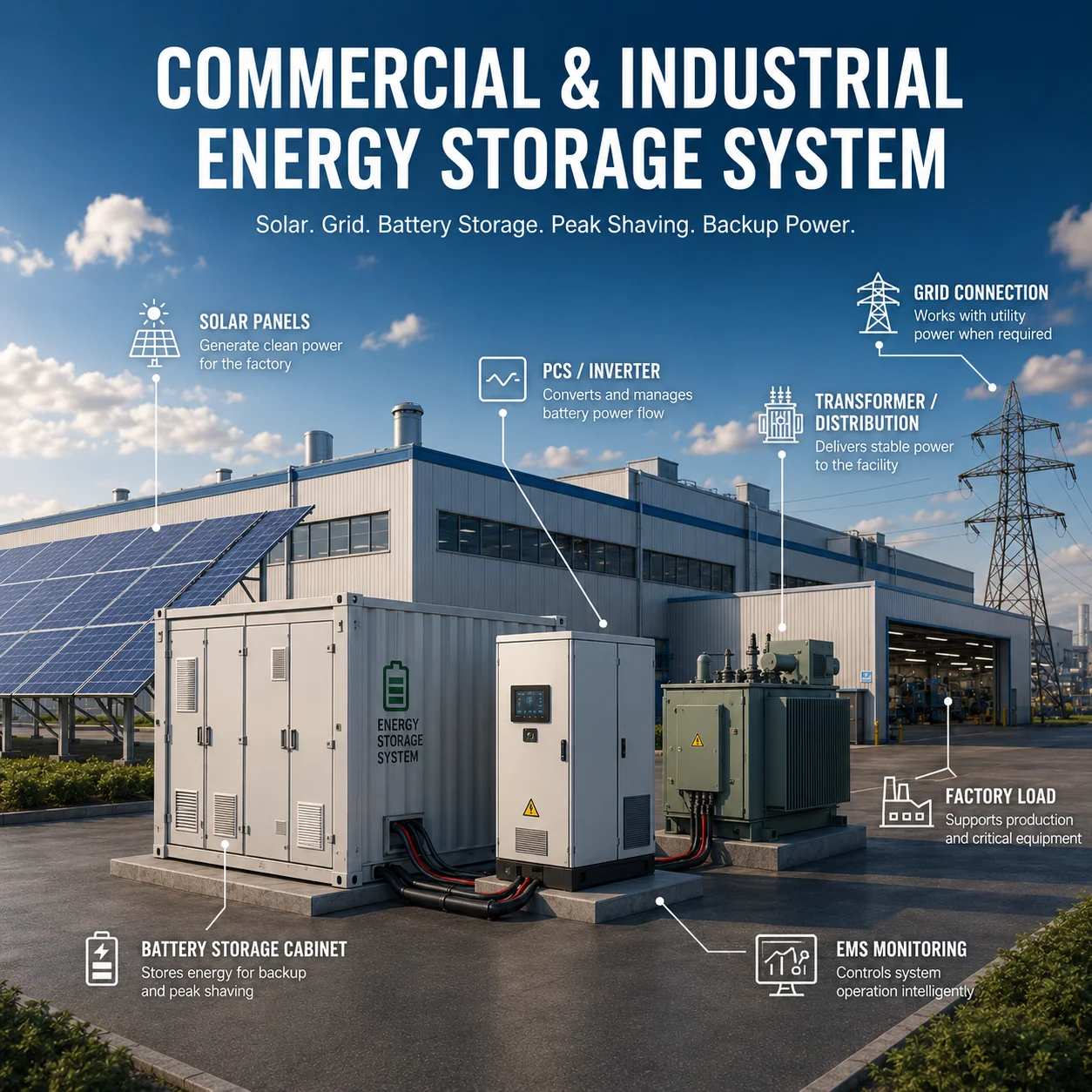
Commercial & Industrial Energy Storage System
At Mars Solar, we know you are not simply looking for a battery cabinet with an attractive capacity rating. You need a complete system that works with the real load, grid conditions, solar capacity, generator, backup time, and operating priorities of your project. That means matching the battery, PCS, BMS, EMS, switchgear, protection, cooling, and monitoring equipment from the beginning. When these parts are coordinated correctly, you avoid oversized investment, communication problems, unstable backup performance, and delays during installation or commissioning.
We support four practical configurations: Grid-Interactive Solar + Storage Backup Systems for facilities affected by frequent outages, Solar + Battery + Diesel Hybrid Microgrids for weak-grid and off-grid projects, New-Build Solar + Battery Hybrid Systems for projects designed with storage from the start, and AC-Coupled Energy Storage Retrofits for existing commercial solar installations. We select the architecture around your load profile and operating goals rather than forcing every project into one standard cabinet package.
Whether you are preparing an EPC quotation, expanding your energy-solution business, adding storage to an existing solar project, or reducing diesel use for a factory, hotel, warehouse, farm, school, or clinic, you have come to the right team. We help organize the solar equipment, lithium batteries, bidirectional PCS, EMS, grid or generator interface, technical documents, and export coordination into one supply-ready solution—so you can quote faster, reduce integration risks, and move the project forward with greater confidence. Mars Solar’s current platform includes industrial battery systems, bidirectional inverters, EMS, smart switching, remote monitoring, and full-load testing before delivery.

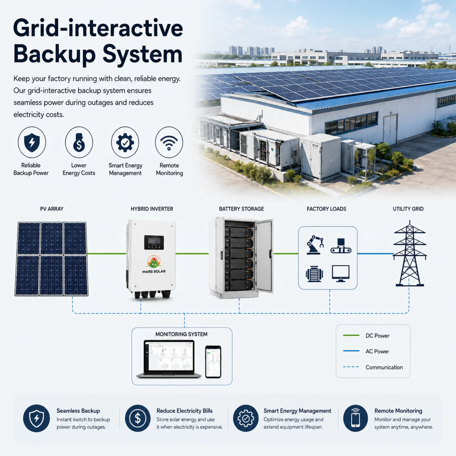
Grid-interactive backup system
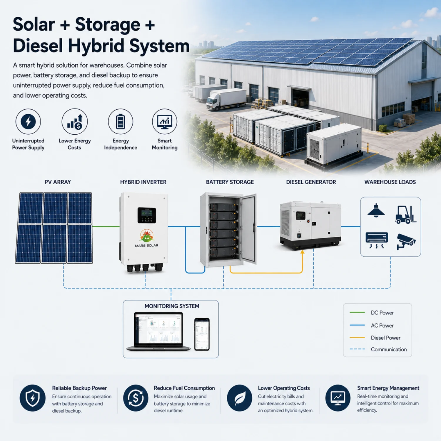
Solar + storage + diesel hybrid system
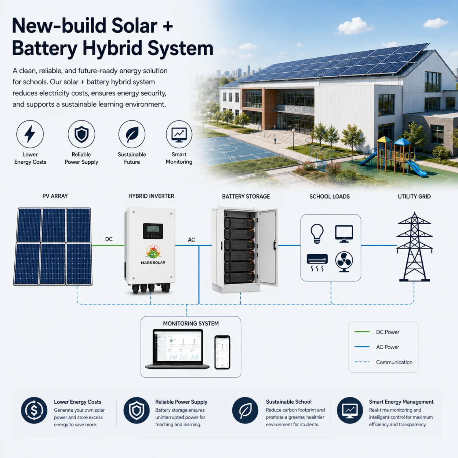
New-build solar + battery hybrid system
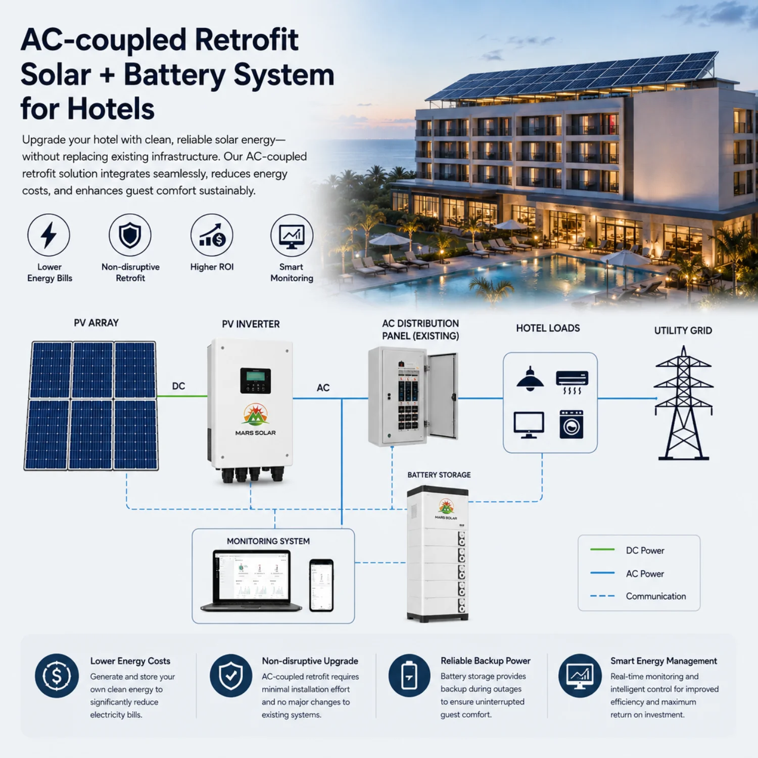
AC-coupled retrofit
Build a Commercial & Industrial Energy Storage System Around Your Real Project
If you already have a factory, hotel, warehouse, farm, commercial building, installation team, or customer waiting for a quotation, you have come to the right team. We understand that you are not looking for another catalogue filled with battery cabinets. You need a partner who can quickly understand the project, match the main equipment, and turn your power requirements into a practical, supply-ready energy storage system.
A C&I energy storage project cannot be defined only by battery capacity. Two projects using the same 215kWh cabinet may require different PCS power, solar capacity, switching equipment, generator controls, and backup strategies. Before proposing a configuration, we review your load profile, critical loads, required backup time, grid conditions, existing solar system, generator capacity, electricity costs, and installation environment. This helps us avoid oversizing, incompatible equipment, and systems that do not operate as expected.
Our Four Core C&I Energy Storage System Configurations
Grid-Interactive Solar + Storage Backup System: This configuration is suitable for factories, hotels, warehouses, schools, clinics, supermarkets, and other facilities affected by frequent grid outages. During normal operation, solar and battery storage help reduce grid consumption. When the grid fails, the system can isolate and continue supplying selected critical loads. We configure the PV system, battery, PCS, EMS, switching equipment, and backup capacity around the loads that truly need continuous power—not simply the total connected load.
Solar + Battery + Diesel Hybrid Microgrid: For weak-grid and off-grid projects, solar, battery storage, and diesel generation must work as one coordinated system. Solar normally supplies the loads first and charges the battery. When solar production falls, the battery supports the site, while the generator starts only when required. We help coordinate the bidirectional PCS, EMS, generator interface, switching equipment, and operating logic to reduce diesel consumption while maintaining reliable power for factories, hotels, farms, mines, and remote facilities.
New-Build Solar + Battery Hybrid System: This configuration is designed for new commercial projects where solar generation and storage are planned together from the beginning. Depending on the project, we may recommend an AC-coupled, DC-coupled, or mixed architecture. We coordinate the solar panels, inverter, battery system, BMS, PCS, EMS, protection, cooling, and monitoring equipment as one package, reducing the compatibility problems that often appear when solar and storage products are purchased separately.
AC-Coupled Energy Storage Retrofit: This is a practical option for customers who already have a grid-connected solar system and want to add battery storage without replacing the original PV equipment. A separate battery and bidirectional PCS are connected to the existing AC system for peak shaving, solar self-consumption, time-of-use management, or backup applications. Before recommending the retrofit, we review the existing inverter, switchboard, transformer, load profile, and required operating mode to confirm that the new storage system can be integrated safely.
Complete Support for Your Project Delivery
A competitive battery price is only one part of a successful project. You also need compatible equipment, a complete BOM, clear technical documents, realistic delivery planning, and responsive support for your local installation team.
Based on your project information, we can help coordinate solar panels, lithium battery cabinets, bidirectional PCS, BMS, EMS, grid and generator interfaces, switchgear, monitoring, cooling, fire-protection equipment, and other system components. Mars Solar’s current platform includes three-phase inverters, industrial battery systems, intelligent energy management, smart grid or generator switching, remote monitoring, and full-load testing before delivery.
Our goal is straightforward: help you understand the project faster, prepare a more reliable quotation, simplify multi-product procurement, and reduce avoidable integration risks. Instead of selling individual products and leaving your team to solve the compatibility problems, we work with you to build a C&I energy storage system that is practical to supply, install, and operate.

More Than a Commercial & Industrial Energy Storage System Supplier
At Mars Solar, we know your profit depends on more than purchasing batteries and PCS equipment at a competitive price. We help you turn real load, backup, solar, grid, and generator requirements into a complete, supply-ready energy storage system—making each project easier to quote, purchase, install, and hand over to your customer.

Win Projects Faster
We organize the load profile, peak demand, critical loads, required backup time, existing solar capacity, grid conditions, and generator information into a practical configuration and complete BOM. This helps you respond faster, present a clearer proposal, and avoid losing projects while waiting for fragmented technical support.
Lower Your Total Project Cost
By coordinating the battery system, PCS, BMS, EMS, switchgear, monitoring, cooling, fire protection, and optional solar or generator interface through one supply process, we reduce repeated communication, separate shipments, missing accessories, and unexpected purchases during installation. You receive a clearer system scope before placing the order.
Protect Your Profit and Reputation
Incorrect battery sizing or incompatible communication between the battery, PCS, EMS, and generator can lead to unstable operation, commissioning delays, and expensive after-sales work. We review the key system interfaces and operating requirements before delivery, helping you control additional costs and provide a more reliable result to your local customer.
Grow with a Stable System Partner
As your business develops, we can support projects ranging from commercial battery cabinets and solar-plus-storage systems to backup systems and solar-battery-diesel hybrid microgrids. You can pursue larger and more complex opportunities without rebuilding your supply chain or searching for a new equipment partner for every project.
Build C&I Energy Storage Projects with More Support Than You Expected
At Mars Solar, we know you may first contact us for a battery price or a standard cabinet configuration. Once we understand your project, however, our role goes much further. We help you clarify the real power requirement, select the right system architecture, coordinate the main equipment, and prepare a solution that is easier to quote, install, commission, and hand over.
Whether you are planning a grid-interactive backup system, a solar-plus-storage project, an AC-coupled retrofit, or a solar-battery-diesel hybrid microgrid, we build the system around how the site actually uses electricity—not simply around a standard battery capacity.
Built Around the Real Load Requirement
Two projects using the same 215kWh battery cabinet can require completely different PCS ratings, backup times, switching equipment, solar capacity, and control strategies. Peak load, critical load, operating schedule, grid stability, existing PV, generator capacity, motor starting current, and electricity tariffs all affect the final configuration.We help you organize this information before confirming the system, allowing the battery, PCS, BMS, EMS, switchgear, solar input, and generator interface to match the real application instead of a generic catalogue package.
More Than a Battery Cabinet
A reliable energy storage project also depends on meters, CTs, distribution cabinets, ATS or STS equipment, cooling, fire protection, communication cables, monitoring, and installation accessories. Missing one interface or protection component can delay commissioning and create unexpected local purchasing costs.We help prepare a clearer and more complete BOM before production, so your team understands what is included, what must be installed locally, and how the main components work together. Mars Solar’s current platform includes industrial lithium batteries, bidirectional inverters, EMS control, smart grid and generator switching, remote monitoring, and full-load testing before delivery.
A Clearer Process from Enquiry to Delivery
We understand how difficult a project becomes when load analysis, system sizing, equipment selection, documentation, pricing, production, and shipment are handled separately. That is why we keep the process connected.We support the project from requirement review and preliminary configuration through technical confirmation, quotation, production coordination, testing, packing, and delivery. Your local team receives more than an equipment price—you gain a clearer route for moving the project from an initial enquiry to a supply-ready system.
Support That Makes Your Next Project Easier
A successful first project should make future quotations and purchases faster. Once we understand your market, common load ranges, preferred voltages, generator conditions, project applications, and installation standards, we can help you develop more repeatable system configurations.Our goal is not simply to complete one battery shipment. We want to give you the technical clarity, supply coordination, and responsive support needed to quote faster, reduce integration risks, deliver more reliable power, and grow your commercial energy storage business with confidence.
C&I Energy Storage Video Insights from Mars Solar
FAQs Commercial & Industrial Energy Storage System
For your convenience, we’ve gathered the most commonly asked questions about our Commercial & Industrial Energy Storage System . However, should you have any further queries, please don’t hesitate to reach out to us.
1. Are you a C&I energy storage manufacturer or a system supplier?
We’re both a product supplier and a system integration partner. We can coordinate lithium battery cabinets, PCS, BMS, EMS, solar equipment, switchgear, monitoring and optional generator interfaces around your project. Instead of leaving you to purchase each component separately, we help bring the main system together under one supply plan.
2. What types of C&I energy storage projects can you support?
We support projects for factories, hotels, warehouses, farms, schools, clinics, supermarkets, mining sites and other commercial facilities. Common applications include backup power, solar self-consumption, peak shaving, diesel reduction, weak-grid support and off-grid power.
3. How do we know what battery and PCS capacity we need?
You don’t need to select the system by guessing from a catalogue. Send us your load profile, peak power, daily consumption, critical loads, backup time, grid conditions, existing solar capacity and generator information. We’ll review how the site actually uses electricity before recommending the battery capacity and PCS rating.
4. Can your system support motors, pumps and other heavy loads?
Yes, but these loads must be checked carefully. Pumps, compressors, chillers and production machines can draw much more power during startup than during normal operation. We review the motor rating, starting method, simultaneous loads and operating schedule to avoid a system that appears large enough but cannot handle real site conditions.
5. Can the system continue supplying power during a grid outage?
Yes, when the system is designed for backup or microgrid operation. This normally requires a grid-forming PCS, suitable switching equipment and clearly defined critical loads. A standard grid-connected battery does not automatically provide backup, so we confirm the operating mode before preparing the configuration.
6. Can you integrate solar panels, the utility grid and a diesel generator?
Yes. We can configure solar-plus-storage systems that also work with the grid and diesel generator. The system can prioritize solar energy, use the battery when needed and start the generator when the battery is low or the load remains high. The exact control method depends on the generator, PCS, EMS and site requirements.
7. Can you work with our existing solar system?
In many cases, yes. For an existing grid-connected PV project, we may recommend an AC-coupled storage retrofit using a separate battery system and bidirectional PCS. Before confirming the solution, we review the existing inverter, AC voltage, transformer, switchboard, export limits and required backup function.
8. Do you provide standard systems or customized configurations?
We provide both. Standard cabinet and container configurations can shorten quotation and production time, while customized systems are available for unusual loads, local voltages, longer backup requirements, generator integration or future expansion. We help you choose the most practical route instead of customizing every project unnecessarily.
9. What testing, documents and technical support can you provide?
Depending on the project scope, we can arrange factory testing, system parameter checks and verification of the main charging, discharging, protection and communication functions. We can also provide datasheets, manuals, preliminary diagrams, packing information and remote technical guidance. Mars Solar’s current platform includes bidirectional inverter technology, EMS control, remote monitoring and full-load testing before shipment.
10. What are the MOQ, lead time and delivery arrangements?
Many complete project systems can be quoted from one set. The final MOQ and production time depend on the battery capacity, PCS, cabinet or container format, customization, certification and component availability. We also support export packing, shipping documents and international delivery coordination, while local surveys, permits, installation and on-site maintenance are normally handled by your local engineering team.








Mars Solar in Numbers
Industry Experience
Since 1000
Countries & Markets
0 +
Manufacturing Facilities
3000 ㎡
Technical & R&D Team
0 +
Systems Supplied or Supported
1500 +
Your Ultimate Guide to Commercial & Industrial Energy Storage System
If you’re planning a C&I energy storage project—whether for a factory, hotel, warehouse, farm, commercial building, or customer site—you’re not simply choosing a battery cabinet. You’re deciding how the site will use solar power, respond to grid outages, reduce diesel consumption, control peak demand, and protect critical operations. Two projects using the same 215kWh battery may require completely different PCS ratings, backup durations, switching equipment, generator interfaces, and EMS strategies. When the operating objective is not defined clearly at the beginning, even good equipment can become oversized, incomplete, or difficult to commission.
Over the past few years, we’ve seen commercial energy storage move from a product-led market into a system-led project category. Buyers are no longer comparing only cell brands, cabinet capacities, and prices. EPC contractors, electrical companies, ESCOs, consultants, and project owners increasingly need to understand how the battery, PCS, BMS, EMS, meters, switchgear, cooling, fire protection, solar inverters, and diesel generators work together. At Mars Solar, our current platform covers industrial lithium batteries, bidirectional power conversion, energy management, remote monitoring, and applicable grid or generator coordination, but we also understand that local surveys, installation, permits, and commissioning responsibilities must be defined for every project.
This guide is built around the questions that appear repeatedly in real C&I projects. Instead of focusing only on battery specifications, we explain how to define the business problem, size PCS power and usable battery capacity, compare AC-coupled, solar-plus-storage, backup, and hybrid microgrid architectures, identify critical loads, prepare a reliable RFQ, review safety and warranty documents, and divide responsibilities between the supplier, EPC contractor, consultant, and project owner. Our goal is to help professional buyers understand what must be confirmed before ordering, which risks are often hidden inside low-price quotations, and how a project can move from an incomplete enquiry to a system that is practical to supply, install, commission, and operate.
Table of Contents
What Does a Complete C&I Energy Storage System Actually Include?
When buyers first compare commercial and industrial energy storage systems, the discussion often begins with battery capacity and cabinet price. A supplier may present a 100kW/215kWh system, while another offers a similar-looking cabinet at a lower price. On the surface, the comparison appears straightforward. In practice, those two quotations may represent completely different supply scopes, technical capabilities and installation requirements.
A battery cabinet is only the energy-storage section of a larger electrical system. To operate reliably at a factory, hotel, warehouse, farm or commercial building, the project may also require a Power Conversion System, Battery Management System, Energy Management System, smart meters, switchgear, cooling, fire protection, remote monitoring, transformers and communication equipment. Some of these components may be integrated into one cabinet, while others must be supplied separately or completed by the local EPC contractor.
From my experience reviewing C&I storage projects, the most important question is not simply how much energy the cabinet can store. The real question is whether the complete system can charge, discharge, protect itself, communicate with the site and perform the intended operating function after installation.
The Battery and BMS Form the Energy-Storage Foundation
The battery is responsible for storing electrical energy, but its headline capacity does not fully describe what the project will receive in real operation. Battery cells are assembled into modules, packs and racks, which are then connected to reach the required system voltage and energy capacity. A system described as 215kWh may have that nominal capacity, but the usable energy will depend on the permitted state-of-charge range, depth of discharge, charging limits, discharging limits, operating temperature, conversion losses, degradation and warranty conditions.
This distinction matters because nominal capacity and usable capacity are not always the same. A project may require two hours of backup for a 100kW critical load, but a nominal 200kWh battery should not automatically be assumed to provide exactly two hours of usable power. Battery reserve settings, system losses and long-term performance protection must also be considered. Two systems with the same advertised capacity can therefore deliver different practical operating results.
The Battery Management System, or BMS, is the internal control and protection layer of the battery. It monitors cell voltage, current, temperature, state of charge and other operating conditions. It also helps prevent overcharging, excessive discharge, overheating, overcurrent and abnormal differences between cells. Cell balancing is especially important because the performance of an entire battery rack can gradually be limited by cells that repeatedly reach their voltage or temperature limits earlier than the others.
A reliable BMS must also communicate correctly with the PCS. When the battery approaches an operating limit, the BMS may instruct the PCS to reduce charging power, reduce discharging power or stop operation. This is one of the most important compatibility points in a commercial BESS. A good battery and a good PCS can still create an unreliable system if their communication protocols, firmware or control logic have not been properly matched and tested.
The PCS Determines How Power Moves Through the System
The Power Conversion System, commonly called the PCS, converts electricity between the battery’s DC side and the facility’s AC electrical network. It allows the battery to charge from the grid, solar system or generator and later discharge energy to the commercial loads or electrical distribution system.
The PCS rating is normally expressed in kilowatts, while battery capacity is expressed in kilowatt-hours. These two figures answer different questions. Battery capacity indicates how much energy can be stored, while PCS power indicates how much electricity can move into or out of the battery at one time. A 100kW/215kWh system may be able to discharge at up to approximately 100kW, but the duration will depend on usable battery energy, conversion efficiency and the actual load profile.
This distinction becomes particularly important in factories and other facilities with motors, pumps, compressors, refrigeration equipment or production machinery. A system may contain enough stored energy for the required operating period but still be unable to support a large starting current. PCS overload capability, motor starting method, simultaneous load demand and short-term power requirements must therefore be reviewed alongside battery capacity.
The operating mode of the PCS must also match the project. A grid-following PCS generally requires an existing grid voltage and frequency reference. It may perform peak shaving or energy shifting while the grid is available, but it will normally stop operating when the grid fails. A grid-forming PCS can establish a local electrical reference for backup or islanded operation, but this function also requires suitable switching, protection and control equipment. For this reason, I do not assume that every commercial battery cabinet can provide backup power simply because it includes a PCS.
The EMS, Meters and Communication Network Control System Behaviour
The Energy Management System, or EMS, determines how the complete storage system should operate. While the BMS protects the battery and the PCS controls power conversion, the EMS applies the project’s operating strategy. It decides when the battery should charge, when it should discharge and how it should interact with solar generation, facility loads, the utility grid and diesel generators.
In a peak-shaving project, the EMS may discharge the battery when facility demand approaches a defined limit. In a time-of-use application, it may charge the battery when electricity prices are lower and discharge during more expensive tariff periods. In a solar self-consumption project, it may store excess daytime PV generation and release that energy later. In a solar-battery-diesel microgrid, it may prioritize solar power, maintain a reserve battery level and start the generator only when the load or battery condition requires it.
The presence of an EMS in a quotation does not automatically mean that every required control function is included. The buyer should understand what the software can control, which devices it can communicate with, how the operating priorities are set and whether the strategy can be adjusted after commissioning. An EMS may support basic charging schedules but not generator synchronization, export limitation or complex load control unless those functions are specifically designed into the project.
Meters, current transformers and sensors provide the data that the EMS uses to make these decisions. The system may need to measure facility consumption, solar generation, grid import, grid export, generator output and battery power. In a peak-shaving project, the meter must detect when the site demand is approaching the agreed limit. In a zero-export application, the meter must identify power flowing toward the utility network and allow the system to respond quickly.
Small measurement errors can create major operating problems. A current transformer installed in the wrong direction can reverse the measured power flow, while a meter installed at the wrong connection point may not represent the total facility load. Meter location, communication settings and current-transformer orientation should therefore be treated as part of the system design rather than as minor installation details.
Communication connects the BMS, PCS, EMS, meters, solar inverter, generator controller and monitoring platform. Interfaces may include CAN, RS485, Ethernet and protocols such as Modbus. What matters is not only the name of the protocol, but whether the required data points and control commands have been correctly mapped. If one communication link is missing, the battery may still charge and discharge, but the generator may not start automatically, export control may fail or the EMS may receive incorrect load information.
Switchgear, Protection and Transformers Connect the BESS to the Site
A storage system cannot be safely connected to a commercial facility without appropriate switchgear and electrical protection. Depending on the project, the required equipment may include AC breakers, DC disconnects, fuses, contactors, surge-protection devices, isolation switches, protection relays, emergency-stop circuits and distribution cabinets.
Backup and microgrid projects require additional attention because the facility must be safely separated from the utility grid before islanded operation begins. This may require an Automatic Transfer Switch, Static Transfer Switch, motorized circuit breakers or another grid-isolation arrangement. The design must prevent the BESS from energizing the public grid during an outage while also allowing critical loads to continue operating.
An all-in-one battery cabinet may contain internal breakers and protection devices, but this does not mean that every site-level component is included. The facility may still require a main BESS distribution cabinet, grid-isolation equipment, transformer protection, critical-load panel or modifications to the existing switchboard. The single-line diagram should make these boundaries clear before the equipment is ordered.
Transformers may also be necessary when the PCS voltage does not match the facility’s electrical network. A commercial PCS may operate at a low-voltage three-phase level, while the project connection point is at another low voltage or at medium voltage. In those cases, the system may require a step-up or isolation transformer, additional switchgear and protection coordination.
The transformer can significantly affect the project cost, footprint, delivery schedule and installation scope. Its rating must consider PCS capacity, expected operating conditions, losses, impedance, temperature rise and possible future expansion. A battery quotation that excludes a required transformer or medium-voltage connection package may therefore represent only part of the real project cost.
Cooling and Fire Protection Affect Safety and Long-Term Performance
Battery performance, ageing and safety are strongly influenced by temperature. A complete C&I energy storage system therefore requires thermal management that matches the battery capacity, enclosure design and local installation environment.
Some commercial cabinets use forced-air cooling, while higher-energy-density systems may use liquid cooling. The objective is not only to prevent overheating. A well-designed cooling system also reduces temperature differences between battery modules. If one section of the cabinet repeatedly operates at a higher temperature, those cells may age faster and gradually reduce the usable performance of the complete system.
The surrounding environment must also be considered. An outdoor cabinet installed in a hot, humid, dusty or coastal region faces different conditions from a system installed in a controlled electrical room. Ambient temperature, direct sunlight, ventilation, humidity, altitude and dust can all influence cooling performance and possible system derating. The published operating-temperature range should therefore be reviewed together with the actual site conditions.
Fire protection must also be assessed at system level. A commercial BESS may contain smoke detection, heat detection, gas detection, alarms, emergency shutdown, ventilation and suppression equipment. However, the equipment installed inside the cabinet is only one part of the final project safety plan.
The installation may still require separation distances, emergency access, site alarms, external fire protection or approval from local authorities, consultants or insurers. A supplier can explain the cabinet-level safety features, but the local project team must confirm what is required for the complete installation. This is particularly important because fire and electrical requirements vary between markets and project types.
Monitoring and Auxiliary Equipment Support Daily Operation
Remote monitoring gives operators visibility into battery state of charge, charging and discharging power, temperature, alarms, grid conditions, solar production and historical performance. For international projects, this can be especially useful because suppliers and technical teams can review operating data without immediately travelling to the site.
Remote access, however, does not replace local maintenance. A failed sensor, damaged cable, cooling problem or mechanical fault may still require physical inspection. The project should define who receives alarms, who can adjust parameters and who is responsible for responding locally. A monitoring platform has limited value if no one is assigned to review and act on the information.
A complete installation may also require auxiliary power supplies, anti-condensation heaters, cabinet lighting, communication gateways, grounding materials, cable trays, glands, connectors and emergency-stop devices. These items receive little attention during early price comparisons, but missing accessories can delay installation and create unexpected local purchasing costs.
A well-prepared bill of materials should distinguish between equipment installed inside the cabinet, accessories shipped separately and materials to be sourced locally. This allows the EPC contractor to prepare the site properly and makes quotations from different suppliers easier to compare.
What Is Normally Supplied from the Factory?
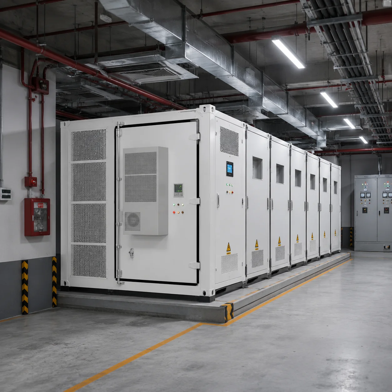
The factory supply scope depends on the system format. A battery-only cabinet may include battery modules, racks, BMS, internal DC protection, cooling and fire protection, while the PCS and EMS are supplied separately. An all-in-one commercial cabinet may integrate the battery, PCS, BMS, EMS, cooling, fire protection, internal wiring and local monitoring into one enclosure. Containerized systems may combine several battery racks with separate power-conversion and control sections.
External transformers, medium-voltage switchgear, main distribution cabinets, transfer switches and generator-control equipment may be optional rather than standard. Even when a product is described as a complete BESS, some site-specific connection equipment may remain outside the standard package.
For this reason, I rely on the detailed BOM, technical proposal and single-line diagram rather than marketing terms such as “all-in-one,” “complete system” or “turnkey cabinet.” These descriptions are used differently across the industry and do not always define the same scope.
The quotation should state what is factory installed, what is supplied separately and what remains the responsibility of the local contractor. It should also explain which components have been communication-tested together and which external devices will require additional integration at the site.
What Usually Needs to Be Completed Locally?
Local work commonly includes the site survey, foundation, civil construction, equipment lifting, cable routing, grounding, switchboard modification and final electrical connection. The local EPC may also be responsible for permits, utility approval, transformer installation, medium-voltage work, critical-load separation and local fire or structural compliance.
Generator wiring and control integration may also require local support, especially when the existing generator controller, ATS or electrical distribution system was supplied by another company. The system supplier may provide interface requirements and control logic, while the local engineer confirms the actual connections and operating sequence.
Commissioning responsibilities should be defined before the order is placed. The equipment supplier may provide parameter settings, factory test records, remote guidance and online troubleshooting, while the local engineering team performs insulation checks, cable verification, switching operations and site acceptance tests.
Clear responsibility boundaries do not weaken the cooperation between the supplier and EPC. They reduce assumptions, prevent duplicated work and make it easier to identify who must resolve a problem if one appears during installation or commissioning.
Why Purchasing a Battery Cabinet Is Not the Same as Purchasing a Complete BESS
A battery cabinet may be well designed, correctly manufactured and fully tested at the factory, but it can still be incomplete for the customer’s specific project. The site may require a different PCS rating, additional switchgear, a transformer, generator controls, an ATS, a microgrid controller or changes to the existing electrical distribution system.
The most useful purchasing question is therefore not simply, “What is the price of this battery cabinet?” A more complete question is, “What equipment, controls, site work and local responsibilities are required to make this cabinet perform the intended function?”
A complete C&I energy storage system is a coordinated combination of energy storage, power conversion, control, protection, thermal management, fire safety, communication and local electrical integration. Each component must match the system voltage, operating strategy, load conditions and site environment.
Once buyers understand this difference, they can compare supplier quotations more accurately, identify missing scope earlier and reduce the risk of receiving equipment that cannot perform as expected after delivery.
Start with the Business Problem, Not the Battery Size
When I review a commercial or industrial energy storage enquiry, the customer often begins with a specific number such as 215kWh, 500kWh or 1MWh. That number may have come from a supplier catalogue, a competitor’s quotation or a product page, but it does not yet explain what the system is expected to accomplish. A factory seeking emergency backup, a hotel trying to reduce diesel consumption and a warehouse managing peak demand may all consider the same 215kWh cabinet, yet each project requires a different PCS rating, operating reserve, switching arrangement and control strategy. For this reason, I prefer to start with the business problem and define the required result before discussing battery capacity. Once the objective is clear, the battery size becomes an outcome of the system design rather than an assumption that controls the entire project.
Why Battery Capacity Alone Cannot Define the System
Battery capacity, measured in kilowatt-hours, indicates how much energy can be stored, but it does not show how quickly that energy must be delivered, how long it must remain available or what should trigger charging and discharging. A 215kWh battery used for peak shaving may need to deliver high power for a relatively short period, while the same cabinet used for emergency backup may discharge more slowly over several hours and maintain a protected reserve throughout the day. In a solar self-consumption project, the battery must leave enough unused capacity to absorb excess daytime generation, while in a diesel-reduction project it may cycle more deeply to keep the generator off for longer. These differences affect the PCS rating, usable state-of-charge range, cycle frequency, battery duration and expected degradation. In my experience, projects become easier to evaluate when the customer first explains the operational problem rather than asking whether a particular cabinet size is “large enough.”
Backup Power Starts with Critical Loads and Outage Duration
When a customer searches for battery storage for a factory or a commercial backup power system, the real concern is usually business continuity. The site may need to protect production controls, refrigeration, communications, lighting, pumps, medical equipment or other essential services whenever the utility grid fails. I do not automatically size the system around the total connected load because many facilities can temporarily disconnect non-essential equipment during an outage. A factory with a total load of 600kW may only need to protect 120kW of critical production and safety equipment, while a hotel may maintain elevators, reception, kitchens and selected guest services without operating every air-conditioning unit. Defining these priorities can reduce unnecessary battery capacity and PCS cost while still protecting the activities that matter most.
A backup system also requires more than stored energy. The PCS must be capable of supporting the critical load, including the starting current of motors, compressors and pumps, while the battery must provide the required operating duration after system losses and reserve settings are considered. The electrical design may also require grid-forming operation, an Automatic Transfer Switch, a Static Transfer Switch or another isolation arrangement that safely separates the protected loads from the utility network. The EMS must preserve enough state of charge for an unexpected outage, even when the battery is also used for daily cost-saving functions. I therefore treat backup power as a complete operating mode involving the battery, PCS, switching equipment, critical-load distribution and control logic, rather than as a feature that can be added to any grid-connected cabinet after the equipment has been selected.
Peak Shaving and Time-of-Use Shifting Solve Different Cost Problems
Peak shaving is mainly a power-control application. The battery discharges when the facility demand approaches a defined limit, helping the customer reduce demand charges, avoid contracted-capacity penalties or prevent an existing transformer from being overloaded. In this type of project, the PCS rating may be more important than long battery duration because the system must respond with enough power at the moment the peak occurs. If the factory demand rises to 650kW and the target is to keep grid import below 500kW, the storage system must provide the missing 150kW. A 100kW PCS cannot fully control that event even when the connected battery contains more than enough stored energy. I therefore review interval load data to understand the height, duration and frequency of the peaks instead of relying only on monthly electricity consumption.
Time-of-use energy shifting has a different objective. The battery charges when electricity is less expensive and discharges during higher-priced tariff periods, so the commercial value depends on the actual tariff difference, battery efficiency, cycling cost and available charging window. The PCS determines how quickly energy can be moved between tariff periods, while the battery capacity determines how many kilowatt-hours can be shifted. The EMS must also prevent charging from creating a new demand peak and avoid discharging too early before the most expensive period begins. A larger battery is not automatically more profitable if the tariff difference is too small or the facility cannot use all the stored energy during peak-price hours. In this application, I begin with the electricity bills and load profile because they reveal how much energy can realistically be shifted and whether the expected savings justify the storage capacity.
Solar Self-Consumption and Export Limitation Depend on Real Surplus Energy
A solar self-consumption system stores PV energy that the facility cannot use at the moment it is generated and releases it later when demand exceeds solar production. The correct battery size should therefore be related to the amount of recoverable surplus rather than the total installed solar capacity. A factory operating continuously during daylight may consume nearly all of its PV generation and leave little energy for storage, while a school, office or warehouse may produce significant excess power during weekends, lunch periods or seasonal reductions in activity. I look at the relationship between the solar-generation curve and the site-load curve to determine when the surplus occurs, how much of it can be captured and whether the evening or nighttime load can use the stored energy.
Export limitation introduces an additional control requirement. When a facility is prohibited from exporting electricity or must remain below a defined export limit, the battery may absorb sudden solar surplus that would otherwise flow toward the utility network. The system needs an accurately positioned meter, correctly installed current transformers, fast communication and enough PCS charging power to respond when PV generation rises or site demand falls. The EMS must also preserve battery headroom because a fully charged battery cannot absorb additional solar energy, regardless of its nominal capacity. In some projects, the control strategy intentionally avoids charging the battery to 100% before the period of highest PV output so that capacity remains available for export control. I therefore see zero-export performance as the result of coordinated metering, PCS response and state-of-charge management, not simply as a software option listed in a product specification.
Diesel Reduction Requires Coordinated Hybrid Operation
In many weak-grid and off-grid markets, the customer’s largest energy problem is not the electricity tariff but the cost of diesel fuel, generator maintenance and fuel transportation. A solar-battery-diesel system can reduce generator operating hours by using solar power first, storing excess generation and allowing the battery to support the loads when solar output falls. The generator then starts only when the battery reaches a defined state of charge, the site load becomes unusually high or prolonged low-solar conditions make additional generation necessary. The objective is not to eliminate the generator regardless of operating conditions, but to use it more efficiently and only when it provides real value.
I do not size this type of project around the battery alone because the generator characteristics strongly influence the system design. The existing generator may have a minimum stable loading requirement, a specific controller, an ATS and operating limits that must be coordinated with the PCS and EMS. Running a large generator at very low load for long periods can reduce fuel efficiency and create maintenance problems, while excessive start-stop cycles may also shorten equipment life. A practical control strategy may start the generator when there is enough site demand or battery-charging requirement to operate it efficiently, then stop it after the battery reaches a defined level. This application may require generator start signals, controller communication, switching equipment, grid-forming PCS capability and clear source-priority logic. Without that coordination, adding a battery cabinet may change where energy is stored but may not significantly reduce diesel consumption.
Weak-Grid Support Requires More Than Emergency Backup
A weak grid may remain connected while experiencing voltage drops, frequency fluctuations, repeated short interruptions or insufficient supply capacity. These conditions are different from a complete blackout, and I avoid treating every form of grid instability as the same technical problem. A storage system may need to limit the power drawn from a constrained utility connection, support the facility during voltage disturbances or disconnect and establish a local microgrid when the grid moves outside acceptable limits. The required response depends on what is happening at the site and which loads are being affected.
PCS capability, protection settings and switching speed are especially important in weak-grid projects. Some commercial equipment can tolerate a short interruption, while sensitive controls, IT systems or continuous processes may require faster support. The battery must also maintain enough reserve for unpredictable grid events while still being available for peak shaving or solar self-consumption. If the system uses all stored energy for daily savings, it may be unable to support the next voltage disturbance. I therefore ask for outage history, voltage records, frequency behaviour and information about the affected equipment whenever possible. The phrase “unstable grid” is a useful starting point, but it must be translated into measurable electrical conditions before the correct operating strategy can be selected.
Off-Grid Operation Must Be Designed as a Complete Energy Balance
In an off-grid project, there is no dependable utility supply to correct a shortage of energy. The solar array, battery, PCS, generator and loads must therefore be balanced across daily operation, seasonal changes and periods of poor weather. I begin by reviewing the daily energy consumption, peak demand, motor-starting requirements, operating schedule and available solar resource. The solar array must produce enough energy to serve daytime loads and recharge the battery, while the battery must support nighttime operation and periods when solar production is below demand. A generator or another backup source may still be necessary for extended cloudy conditions, maintenance or unexpected load growth.
Oversizing the battery alone does not make an off-grid system more reliable. A large battery may remain partly empty if the PV array cannot recharge it, while an oversized solar array may be curtailed when the loads and battery cannot absorb the available generation. Load management can often improve the design more effectively than simply adding storage capacity. Pumps, refrigeration, water heating or processing equipment may be scheduled during strong solar periods, allowing critical loads to receive continuous priority without requiring every kilowatt-hour to pass through the battery. I therefore view off-grid design as an energy-balance problem across hours and seasons. The final battery size should reflect the agreed reliability target, acceptable generator runtime and realistic charging conditions rather than an arbitrary number selected from a product catalogue.
Most C&I Projects Combine Several Operating Objectives
A real commercial project rarely has only one goal. A factory may want emergency backup, peak shaving and higher solar self-consumption, while a hotel may want to reduce diesel use and protect essential services during outages. A warehouse may need to prevent solar export during the day and shift stored energy into a more expensive evening tariff period. These functions can compete for the same battery capacity, so the project needs a clear priority order.
Solar self-consumption requires unused battery space to absorb excess PV, while backup power requires stored reserve. Peak shaving requires energy to be available before the next demand event, and diesel reduction may require deeper cycling to keep the generator off. I normally begin by identifying which outcome has the greatest operational or financial importance. Safety and critical-load continuity may receive the highest priority, followed by export limitation, peak control and tariff optimization. The EMS can then divide the battery’s operating range into zones that protect emergency reserve while allowing part of the capacity to create daily savings. Without this hierarchy, the system may technically support several functions but fail to deliver the one result the customer values most.
How the Objective Changes the System Configuration
The operating objective influences nearly every major technical decision. Backup power requires sufficient PCS capacity for the critical loads, adequate battery duration, protected reserve energy and suitable grid-isolation equipment. Peak shaving usually places more emphasis on high discharge power, rapid meter response and the duration of load peaks. Time-of-use shifting depends on the amount of energy moved between tariff periods and the time available for charging. Solar self-consumption is determined by actual PV surplus and later site demand, while export limitation requires rapid charging response and reliable measurement at the grid connection point.
Diesel reduction requires generator communication, grid-forming capability and a controlled operating sequence. Weak-grid support requires appropriate protection, switching and reserve capacity, while off-grid operation requires the complete balance of generation, storage, backup sources and load management. The same battery cabinet may appear in several of these systems, but its PCS rating, state-of-charge limits, switching equipment and EMS logic can be substantially different. I therefore treat the business objective as the design brief that gives meaning to the equipment specification. Without that brief, the quotation may describe what the supplier can sell but not what the project actually needs.
Define the Required Result Before Selecting the Battery
Before discussing cabinet models, I prefer to translate the customer’s concern into a measurable operating target. Instead of saying that a factory needs backup power, the requirement may be to maintain 120kW of critical load for three hours. Instead of requesting peak shaving, the target may be to keep utility demand below 500kW during the production shift. A solar self-consumption project may aim to store 250kWh of daily surplus, while a diesel-reduction project may seek to reduce generator operation from eighteen hours to six hours per day.
Once the result is measurable, the PCS rating, usable battery duration, reserve level, switching arrangement and control strategy can be selected around it. Starting with a battery size may produce a quotation quickly, but it can also lock the project into an assumption that has never been tested against the real load, tariff or operating conditions. In my experience, the most successful C&I energy storage projects are not necessarily those with the largest batteries. They are the projects in which the business problem is clearly defined first and every part of the system is then configured to deliver the result that matters.
How to Size C&I Battery Capacity and PCS Power Correctly
When a factory, hotel, warehouse or commercial facility asks how many kilowatt-hours of battery storage it needs, the question often begins with a standard cabinet size such as 100kW/215kWh, 250kW/500kWh or 500kW/1MWh. I understand why buyers begin this way, because these numbers are easy to compare across quotations. However, they do not tell me whether the system can support the required load, handle motor starting, meet the expected backup duration or recharge before the next operating cycle. Correct C&I battery sizing requires power, energy and time to be evaluated together. The PCS must deliver enough kilowatts at the moment the load needs them, while the battery must contain enough usable kilowatt-hours to sustain that output for the required period. Some systems have plenty of stored energy but cannot supply the site’s peak power, while others have a large PCS but insufficient battery capacity to maintain the load for long enough. For this reason, I always begin with the load profile and operating objective rather than selecting a standard battery cabinet first.
Understanding PCS Power and Battery Capacity
PCS power is measured in kilowatts and describes how much power the battery system can charge or discharge at one moment. Battery capacity is measured in kilowatt-hours and describes how much energy can be stored over time. I often explain the difference by saying that PCS power determines how strongly the system can support the load, while battery capacity determines how long that support can continue. A 100kW/215kWh BESS therefore combines a PCS capable of supplying approximately 100kW with a battery containing approximately 215kWh of nominal energy. Under ideal mathematical conditions, the system appears able to deliver 100kW for slightly more than two hours, but a real project cannot use the full nominal capacity without considering state-of-charge limits, conversion losses, battery reserve, temperature and degradation. The same 215kWh battery connected to a 50kW PCS may operate for longer at a lower load, but it cannot support a 100kW requirement. If it is connected to a 200kW PCS, it may provide more power, but the battery will discharge much faster and must also be technically approved for that higher discharge rate. This is why kilowatts and kilowatt-hours should never be treated as interchangeable figures.
Separating Peak Load, Average Load and Critical Load
The most reliable sizing process begins by separating peak load, average load and critical load because each figure affects a different part of the system. Peak load is the highest power demand that the PCS may need to support, including short periods when several machines operate together or when pumps, compressors and motors start. Average load is the typical sustained power consumption and is more useful for calculating how quickly the stored battery energy will be consumed. Critical load is the part of the facility that must remain powered during an outage, which may be much smaller than the total connected load. A factory might have a total peak demand of 500kW but require only 140kW of production controls, refrigeration, safety equipment, pumps and communication systems during a blackout. If the complete 500kW load is used for sizing, the project may become unnecessarily expensive; if only the average load is considered, the PCS may fail when a temporary peak occurs. I therefore review both the sustained load and the highest expected short-term demand, while also confirming which equipment genuinely requires backup.
Calculating Battery Capacity from Backup Duration
Backup duration should be calculated from the real load that must operate during an outage rather than from the facility’s total nameplate capacity. If a factory needs to support 100kW of critical load for two hours, the theoretical energy requirement is 200kWh. In practice, a nominal 200kWh battery would normally be insufficient because the full nameplate capacity is not always available to the load. If the battery operates within a limited state-of-charge range, part of its capacity remains unused for protection or reserve, and the PCS and internal equipment also consume energy during conversion. Battery ageing gradually reduces available capacity as well, so a system that barely meets the target when new may fall below it later. I therefore calculate the nominal battery requirement by considering the required load energy, usable state-of-charge window, system efficiency, operating reserve and expected long-term degradation. The load may also change during the outage. A hotel might require 150kW immediately after grid failure but fall to 90kW after non-critical air-conditioning is disconnected, while a factory may need higher power briefly to complete a process before moving into a lower emergency operating mode. In these cases, dividing the outage into realistic operating stages produces a more accurate capacity calculation than assuming one constant load for the entire period.
Why Usable Capacity Matters More Than Nameplate Capacity
The capacity shown on a battery cabinet is usually its nominal capacity, but the figure that determines real operating duration is usable capacity. A nominal 215kWh battery operating between 10% and 90% state of charge has an 80% operating window before conversion losses are considered. If the system must preserve an additional emergency reserve, even less energy may be available for daily peak shaving, tariff shifting or solar self-consumption. Temperature can also cause the BMS to reduce charging or discharging power, while long-term cycling gradually lowers the total available energy. For this reason, I avoid describing a 215kWh system as having a guaranteed two-hour duration at 100kW unless the calculation includes the permitted depth of discharge, PCS efficiency, reserve setting and end-of-life performance requirement. A project that must still provide two hours of backup several years later may need additional nominal capacity at the beginning. The correct allowance depends on the selected battery chemistry, warranty terms, operating temperature, cycle frequency and state-of-charge strategy, rather than on one universal oversizing percentage.
Matching Charging and Discharging Limits to the Application
Even when a battery contains enough energy, it may not be able to charge or discharge at the rate required by the project. The permitted rate depends on the cell design, battery voltage, BMS settings, temperature, PCS capacity and C-rate. A 200kWh battery discharging at 100kW operates at approximately 0.5C, which corresponds to a theoretical two-hour discharge. The same battery discharging at 200kW operates at approximately 1C and would theoretically last about one hour, provided the battery is designed for that rate. Higher discharge power can increase heat and cell stress, so the battery’s continuous and short-term current limits must match the PCS rather than being assumed from capacity alone. Charging power deserves the same attention. If a 400kWh battery must recover its usable energy during a four-hour off-peak tariff window, a 50kW PCS may not recharge it quickly enough. In a solar project, the available PV surplus may limit charging even when a larger PCS is installed, while in a generator-assisted system, excessive charging demand may overload the generator or force it into an inefficient operating range. I therefore evaluate charging and discharging separately according to the actual operating schedule.
A Simple Factory Backup Sizing Example
Consider a factory with a total connected load of 450kW. After reviewing the equipment list, the essential loads include 60kW of production controls and machinery, 25kW of refrigeration, 15kW of lighting and communications, and 20kW of pumps and auxiliary equipment, creating a sustained critical load of approximately 120kW. The customer wants two hours of backup, so the theoretical load energy is 240kWh. If only 90% of the nominal battery capacity is usable and the complete conversion path is approximately 95% efficient, the nominal battery requirement is already closer to 281kWh before any allowance for emergency reserve or future degradation. The PCS must also be larger than the sustained 120kW load if a pump or compressor creates a temporary startup demand. If one pump adds a 70kW starting requirement, the project may need a PCS with sufficient short-term overload capability, or the local engineer may reduce the starting current through a soft starter, variable-frequency drive or controlled starting sequence. A standard 100kW/215kWh cabinet would not meet this project because its PCS is below the 120kW sustained critical load and its usable energy is below the two-hour requirement. The cabinet may be suitable for another site, but it is not suitable for this load profile.
What a 100kW/215kWh BESS Really Means
A 100kW/215kWh BESS is often described as a two-hour commercial storage system, but I treat that description as a simplified category rather than a guaranteed operating result. For peak shaving, the system may discharge at 100kW for short intervals whenever grid demand exceeds a defined limit. If each event lasts only thirty minutes, approximately 50kWh is used before losses, leaving capacity for additional events. For backup power, a sustained 100kW critical load would result in less than two hours of practical operation once usable capacity, reserve settings and conversion losses are applied. If the critical load is 60kW, the duration can be longer, but it should still be calculated from usable energy rather than by dividing the full 215kWh nameplate value by 60kW. In a solar self-consumption project, the same system might store excess midday generation and discharge in the evening, but its commercial value would depend on whether the facility produces enough solar surplus to charge the battery and has enough later demand to use the stored energy. The equipment rating remains the same, yet the correct interpretation changes with the operating objective.
Avoiding Power-Rich but Energy-Poor Systems
One common sizing error is selecting enough PCS power without providing enough battery duration. A warehouse may require 200kW of backup for two hours and receive a proposal for a 200kW PCS connected to a 215kWh battery. The system can technically deliver the required power, but the battery would theoretically last only slightly more than one hour at full output and less after real operating limits are included. To support 200kW for two hours, the project requires more than 400kWh of usable energy and therefore a higher nominal battery capacity after reserve, efficiency and degradation are considered. The opposite mismatch also occurs when a large battery is paired with a small PCS. A 500kWh battery connected to a 100kW PCS may provide long duration at lower power, but it cannot support a 180kW critical load regardless of how much energy remains stored. These examples show why PCS power and battery energy must be checked independently before being combined into one system rating.
Motor Starting and Short-Term Peaks
Industrial and commercial sites often contain pumps, compressors, chillers, conveyors, elevators and refrigeration equipment whose startup demand is much higher than their normal running power. A 30kW motor does not necessarily create only a 30kW demand when it starts. Depending on the motor and starting method, the temporary current may be several times higher, which can overload or trip a PCS that was sized only from steady-state consumption. I therefore ask for the motor rating, starting method, starting sequence and whether several large loads may start simultaneously. The PCS datasheet must be reviewed for short-term overload capability as well as continuous power. In some cases, increasing the PCS is necessary, but in others the more economical solution is to install a variable-frequency drive, use a soft starter, stagger the starting sequence or remove certain motors from the protected load group. Good system sizing is not simply a matter of adding more battery and inverter capacity; it also involves understanding and improving the way the facility operates.
Why Standard Cabinet Recommendations Are Often Misleading
Standardized C&I cabinets are useful because they simplify manufacturing, transportation, testing and installation, but they should be treated as building blocks rather than universal solutions. A 100kW/215kWh cabinet may be an excellent match for one factory, too small for another and unnecessarily large for a third. The correct answer depends on the site’s peak demand, critical load, backup duration, charging window, available solar surplus and future expansion plans. When buyers begin with a fixed product model, there is a risk that the project requirements will be adjusted to fit the cabinet rather than the cabinet being selected to fit the project. Backup duration may be shortened, motor starting may be ignored or nominal capacity may be mistaken for usable capacity simply because the selected model produces a more attractive initial quotation. I prefer to complete the load analysis first and then decide whether the project needs one standard cabinet, several parallel cabinets or a different relationship between PCS power and battery capacity.
The Load Data Needed for Reliable Sizing
A monthly electricity bill is useful, but it does not provide enough detail for accurate PCS and battery sizing. The most valuable information is interval load data showing how power demand changes during the day. Fifteen-minute or thirty-minute records can reveal sustained consumption, production peaks, low-load periods and the duration of demand events. For backup systems, I also need a clearly defined critical-load schedule and realistic outage duration. Motor-heavy facilities should provide starting information, while solar-storage projects require the PV generation curve to be compared with the site-load curve. Time-of-use applications need the tariff schedule and available charging window. When detailed monitoring data is unavailable, preliminary sizing can begin with equipment ratings, operating hours, electricity bills and customer interviews, but the assumptions should be recorded and later verified through site measurement. Better data does not make the design unnecessarily complicated; it reduces uncertainty and allows every major system rating to be connected to a real operating condition.
Sizing for Future Expansion and Long-Term Performance
C&I storage equipment may remain in service for many years, while a factory, hotel or warehouse can change its operating load much sooner. A new production line, additional refrigeration equipment or a property expansion may increase both peak power and daily energy consumption. I therefore ask whether future growth is confirmed, planned or only possible. This does not always justify installing all future battery capacity immediately, because an oversized first phase may reduce project economics. A modular design may be more practical, provided the original PCS architecture, switchgear, transformer, communication network and EMS can support later expansion. Battery degradation should also be considered over the required operating life. If the system only meets the customer’s backup target when new, it may fall below that target after several years. Long-term sizing should distinguish between present demand, realistic future growth and the capacity needed to maintain the agreed performance at the end of the warranty period.
Begin with a Measurable Operating Target
Correct sizing begins by converting the customer’s requirement into a measurable result. The project may need to support 120kW of critical load for two hours, limit grid demand to 500kW, absorb 180kWh of daily solar surplus or discharge 150kW during a two-hour high-tariff period. Once that target is clear, the PCS can be selected according to the highest required charging or discharging power, including short-term peaks, while the battery capacity can be calculated from the required energy duration and adjusted for usable state of charge, efficiency, reserve and degradation. This process is more reliable than selecting a cabinet first and asking whether it is large enough. In my experience, correct C&I energy storage sizing is not about choosing the largest battery or the highest PCS rating. It is about matching power, energy and operating time to the way the facility actually uses electricity.
AC-Coupled, DC-Coupled, Backup or Hybrid Microgrid: Which Architecture Fits the Project?
When I review a commercial solar and battery project, I do not begin by asking which architecture is more advanced. I begin by looking at what already exists at the site, what the customer wants the system to achieve, how reliable the utility grid is, whether diesel generators are involved, and what the system must do during an outage. An existing factory with a functioning grid-tied PV installation has very different integration requirements from a new hotel being designed with solar and storage from the beginning. A remote farm or industrial facility that depends on diesel generation requires another level of power-source coordination. The architecture should therefore follow the actual site conditions rather than the supplier’s preferred product platform.
This is an important distinction because suppliers sometimes recommend the configuration they already manufacture instead of the one that best fits the project. A battery cabinet may be described as AC-coupled, hybrid or microgrid-ready, but the product label does not prove that it can communicate with the existing solar inverter, support critical loads during an outage, control a generator or comply with the site’s electrical design. I treat the architecture as a project-level decision involving the battery, PCS, solar inverter, EMS, switchgear, transformer, generator controls and local installation scope. The following four configurations represent the most practical options for commercial and industrial projects.
AC-Coupled Energy Storage Retrofit
An AC-coupled energy storage retrofit is usually the most practical solution when the site already has an operating grid-connected solar system. The existing PV array and solar inverter remain connected to the facility’s AC distribution network, while a separate battery system and bidirectional PCS are added to the same AC bus. This allows the original solar investment to remain in service while storage is introduced for peak shaving, time-of-use energy shifting, solar self-consumption or export limitation. I often consider this approach for factories, warehouses, hotels, schools and commercial buildings that installed solar several years earlier and now want to capture excess generation or improve their energy-management capability without replacing the existing PV inverters. Its main advantage is retrofit flexibility, but the project must accept some additional conversion losses because solar electricity may be converted from DC to AC, then back to DC when charging the battery, and finally to AC again during discharge. The more important limitation is that a standard AC-coupled system does not automatically provide backup power. If the existing PV inverter and battery PCS are grid-following, both may stop when the utility supply fails. Backup operation may require a grid-forming PCS, grid-isolation equipment, a protected-load panel and control logic that allows the solar system to continue operating inside a local microgrid. Before selecting this architecture, I need to review the existing inverter models, AC voltage, transformer capacity, main switchboard, point of connection, export restrictions, facility load profile and required operating functions.
New-Build Solar-Plus-Storage System
A new-build solar-plus-storage project allows the PV generation, battery capacity, inverter platform and control strategy to be designed together from the beginning. Depending on project size and equipment selection, the system may use DC coupling through a hybrid inverter or shared DC bus, or it may use separate PV inverters and battery PCS units coordinated through an AC bus. I consider this configuration suitable for new factories, hotels, warehouses, farms, agricultural processing facilities, schools and commercial developments where storage is already part of the first project phase. A DC-coupled or integrated hybrid design can reduce some conversion stages and allow excess solar energy to charge the battery before it reaches the AC network, while a larger AC-bus design may provide more flexibility, redundancy and easier equipment replacement. The main challenge is compatibility because the PV voltage, battery voltage, charging current, BMS protocol, inverter firmware and EMS must all work together. Future expansion also needs to be considered because the original inverter capacity, DC-bus limits, switchgear and control platform may restrict the addition of more solar panels or battery racks later. I therefore avoid assuming that DC coupling is automatically better for every new project. The architecture should be selected after reviewing the planned solar capacity, load profile, battery objective, required backup duration, grid conditions, available installation space, system voltage, maintenance strategy and realistic expansion plans.
Grid-Interactive Backup System
A grid-interactive backup system is designed for commercial sites that want to reduce normal electricity costs while also maintaining selected loads during utility outages. During grid-connected operation, the battery may support peak shaving, solar self-consumption or tariff shifting. When the grid fails, the system isolates a protected section of the facility and uses the battery and available solar generation to maintain critical operations. I see this configuration as particularly relevant for factories, hotels, warehouses, clinics, schools, supermarkets and cold-storage facilities in markets where the grid exists but is unreliable. The most important design decision is not the battery cabinet size but the critical-load boundary. A factory with an 800kW total load may need to protect only 180kW of production controls, refrigeration, communications and safety equipment, while a hotel may maintain elevators, reception, lighting and essential guest services without backing up every air-conditioning unit. Backup operation also requires more than installing an ATS beside the battery. The PCS must be capable of grid-forming operation, the protected loads must be separated safely from the utility network, and the EMS must manage the transition between grid-connected and islanded operation while preserving sufficient battery reserve. Motor starting, transfer time and load sequence must also be considered because compressors, pumps, chillers and elevators may create much higher temporary demand than their normal running power. Before selecting this architecture, I need the peak load, average load, critical-load schedule, motor-starting information, required backup duration, switchboard arrangement, existing solar capacity, grid voltage and acceptable transfer time.
Solar-Battery-Diesel Hybrid Microgrid
A solar-battery-diesel hybrid microgrid is normally the most appropriate architecture when the site has no reliable utility supply or depends heavily on diesel generators. Solar generation, battery storage, generators and any available grid connection are coordinated through an EMS or microgrid controller so that each source operates according to a defined priority. I often see this requirement in remote factories, commercial farms, mining sites, telecom facilities, agricultural processing plants, hotels, schools and clinics where fuel cost, generator maintenance and power interruptions directly affect operations. During strong solar production, PV supplies the load and charges the battery. When solar output falls, the battery supports the site and absorbs short-term load changes. The generator starts only when the battery reaches a defined state of charge, the load becomes too high or prolonged low-solar conditions require additional energy. The system can then use the generator to support the load and, where appropriate, recharge the battery before shutting it down again. The main limitation is integration complexity. The generator’s rated power, minimum stable load, controller type, start-stop interface and synchronization method must be coordinated with the PCS, EMS, switchgear and battery reserve strategy. A large generator operating continuously at very low load may be inefficient and experience maintenance problems, while excessive starting and stopping may also be undesirable. Before selecting this architecture, I need the full load profile, generator specifications, controller model, daily fuel consumption, minimum acceptable generator runtime, available solar resource, grid availability, expected reserve level and local commissioning capability.
How the Four Architectures Differ in Real Projects
The four configurations may use similar battery cabinets, but their project responsibilities are very different. An AC-coupled retrofit is mainly designed to preserve an existing PV investment and add storage with limited changes to the solar system. A new-build solar-plus-storage project allows solar generation and battery charging to be planned together, but it requires tighter compatibility between the battery, inverter and control platform. A grid-interactive backup system adds the ability to maintain selected loads during outages, which introduces grid-forming requirements, transfer equipment, critical-load separation and islanding protection. A solar-battery-diesel microgrid goes further by coordinating several power sources and controlling when the generator should start, stop, synchronize and recharge the battery. A 100kW/215kWh cabinet used for peak shaving therefore cannot be treated as equivalent to the same cabinet used for backup or generator reduction. The battery capacity may be identical, but the PCS function, switching arrangement, EMS logic, protection system and commissioning scope can be substantially different.
Information I Need Before Selecting the Architecture
Before recommending any architecture, I first confirm whether the project has an existing solar system and review its inverter models, capacity, output voltage and point of connection. I then examine the facility’s peak load, average load, critical loads, daily operating schedule, motor-starting requirements and expected future expansion. Grid conditions are equally important because a reliable grid, a weak grid and a site with no utility connection require different control and protection strategies. Where backup is required, I need to understand the expected outage duration, acceptable transfer time and whether the customer wants full-site or critical-load support. Where generators are involved, I review the generator capacity, controller, ATS, minimum loading, operating hours and fuel consumption. I also clarify the local project scope, including who will complete the site survey, electrical design, transformer work, switchgear installation, programming, testing and commissioning. An architecture can be technically possible but still unsuitable if the local engineering team cannot install or maintain it reliably.
Choosing the Architecture Around the Required Result
I prefer to define the result before naming the architecture. If the customer wants to add storage to an existing grid-tied PV system for peak shaving or solar self-consumption, an AC-coupled retrofit is often the practical starting point. If the project is new and solar generation and battery storage can be designed together, a purpose-built solar-plus-storage system may provide better coordination. If the facility must maintain critical loads during utility outages, the design needs a grid-interactive backup architecture with grid-forming and safe isolation capability. If the site relies on diesel generators or has little dependable grid access, a solar-battery-diesel hybrid microgrid is usually the more appropriate direction. The most complex architecture is not automatically the best because every additional control function creates more communication points, protection requirements and commissioning responsibilities. In my experience, the most reliable C&I projects are those where the architecture follows the existing electrical system, load behaviour and business objective rather than the supplier’s standard product package.
How Solar, Grid, Battery and Diesel Generators Work Together
A commercial hybrid power system is not created simply by connecting solar panels, a battery cabinet, the utility grid and a diesel generator to the same site. Each source has different operating characteristics, response times and cost implications, so the project needs a clearly defined sequence that determines which source supplies the load first, when the battery charges or discharges, when the generator starts, how critical loads are protected and what happens when the grid fails or returns. In practice, this operating logic is what separates a collection of compatible products from a stable commercial microgrid. The battery, PCS, EMS, meters, generator controller and switching equipment must exchange accurate information and follow the same control strategy; otherwise, individually reliable products can still create unstable transfers, unnecessary generator starts, battery shutdowns or interruptions to the customer’s operations.
Solar Supplies the Load Before Other Energy Sources
In most solar-battery-diesel systems, solar generation is normally given first priority because using solar electricity directly avoids fuel consumption, reduces grid purchases and prevents unnecessary battery cycling. When the solar array is producing less power than the facility requires, the remaining demand can be supplied by the battery, grid or generator according to the project objective. A grid-connected factory may allow the utility supply to cover the shortfall while preserving battery capacity for peak shaving or outages, whereas a weak-grid hotel may discharge the battery first to reduce dependence on unstable grid power. At an off-grid site, the battery may support the load until it reaches a defined reserve level, after which the generator starts. Solar priority therefore does not mean that solar works alone; it means the EMS uses available PV energy first and coordinates the remaining sources according to cost, reliability and battery-reserve requirements.
Excess Solar Charges the Battery
When solar production is higher than the facility load, the surplus energy can be directed into the battery instead of being exported or curtailed. The amount that can actually be stored depends on the available solar surplus, PCS charging power, battery state of charge, BMS limits, battery temperature and the permitted charging rate. If the site has 120kW of surplus PV but the PCS can charge at only 80kW, part of the remaining solar generation may still need to be exported or curtailed. The EMS must also decide how much empty battery capacity should be preserved for later solar production. In a zero-export project, the system may intentionally avoid fully charging the battery early in the morning so that it can absorb stronger midday generation. In a backup-focused project, the controller may first charge the battery to a protected emergency reserve before using the remaining capacity for normal energy optimization. The battery-charging strategy must therefore reflect both the current solar surplus and the functions the system will need to perform later in the day.
The Battery Covers Short-Term Shortages and Fast Load Changes
The battery is generally the fastest responding source in a commercial microgrid, making it suitable for covering passing clouds, sudden load increases and the time required for a generator to start and stabilize. If solar output drops quickly or a compressor begins operating, the PCS can increase battery discharge almost immediately, provided it has sufficient continuous and short-term overload capability. This rapid response allows the generator to run less frequently and at a more stable output instead of constantly following every small variation in the load. Battery support must still respect the project’s reserve strategy because the system may need to preserve enough energy for an unexpected outage or generator-start failure. When available energy becomes limited, the EMS may continue supporting refrigeration, communication, safety systems and production controls while disconnecting non-critical loads. A well-configured battery therefore does more than store solar electricity; it stabilizes the power balance and gives the slower energy sources time to respond without interrupting essential operations.
The Generator Starts According to Battery Condition and Site Demand
A diesel generator should normally start before the battery reaches its lowest protection limit because the system needs enough remaining energy to maintain the load while the generator starts, reaches stable voltage and frequency and connects to the microgrid. The start decision is commonly based on battery state of charge, but a reliable strategy also considers facility demand, solar availability, generator efficiency and expected operating conditions. The EMS may request a generator start when the battery reaches 25% state of charge and solar production is insufficient, but it may start earlier if the load is unusually high or delay the start if the load is light and strong solar production is expected soon. The stop condition should also be separated from the start threshold so that the generator does not repeatedly switch on and off around one battery level. In many projects, the generator supplies the facility load and charges the battery simultaneously, allowing it to operate at a more efficient load before stopping after the battery reaches a higher target state of charge.
The EMS Coordinates Energy Sources and Load Priorities
The Energy Management System acts as the decision-making layer for the complete hybrid system. It receives battery information from the BMS, charging and discharging status from the PCS, grid and load measurements from meters, solar-production data from the PV inverter, generator status from the generator controller and switch positions from the ATS, STS or motorized breakers. Based on this information, the EMS decides whether solar, battery, grid or diesel should serve the load and how much power each source should provide. It must also manage load priorities because available generation may not always be sufficient for the entire facility. A factory may preserve production controls, safety systems and essential pumps while stopping non-critical machinery, while a hotel may maintain reception, elevators, lighting and communications while reducing air-conditioning demand. The control strategy should also define fallback behaviour for communication failures, meter faults and abnormal equipment conditions so that the system enters a predictable safe mode rather than continuing to operate with incomplete information.
The PCS Must Support the Required Grid and Microgrid Modes
The Power Conversion System determines how electricity moves between the battery and the AC network, but its required capabilities depend on the operating architecture. A grid-following PCS can normally charge and discharge while the utility grid is present because it uses the grid as its voltage and frequency reference. A backup or off-grid microgrid generally requires a grid-forming PCS that can create and maintain a stable local AC network when the utility supply and generator are unavailable. This distinction should be confirmed before ordering because a standard grid-connected PCS may stop as soon as the grid fails, even though the battery still contains energy. The PCS must also have enough continuous output and overload capability to support the selected loads, including pumps, compressors, refrigeration equipment and other motors with high starting demand. Communication with the BMS is equally important because the battery may reduce its permitted charging or discharging current in response to temperature, state of charge or another protection condition. Similar voltage ranges do not guarantee that a battery and PCS can exchange the correct operating limits, so protocol and firmware compatibility must be verified at system level.
Generator Controllers Must Be Checked Before Integration
Generator integration cannot be confirmed only by stating that the energy storage system supports automatic start and stop. The real capability depends on the generator brand, controller model, communication interface, existing ATS arrangement, output voltage, minimum stable load and synchronization method. Some generator controllers provide Modbus communication, allowing the EMS to read operating status, alarms, electrical measurements and other information, while older systems may offer only dry-contact start and stop signals. A dry contact can support basic operation, but it does not provide the same level of monitoring, confirmation and coordinated control. The project must also determine whether the generator will synchronize with a battery-created microgrid or whether the loads will transfer between the two sources through a controlled switching sequence. These differences affect the communication gateway, protection settings, control panel and commissioning work, which is why generator details should be reviewed before equipment production rather than discovered after delivery.
ATS and STS Equipment Control Safe Source Transfer
An Automatic Transfer Switch and a Static Transfer Switch both manage changes between power sources, but their transfer behaviour is different. An ATS uses mechanical switching and may create a noticeable interruption as the site moves between the utility grid, generator and backup bus, while an STS can transfer much faster through electronic switching. The appropriate choice depends on the loads rather than on the assumption that the fastest option is always necessary. Pumps, lighting and many mechanical systems can tolerate a brief interruption, whereas sensitive process controls, servers, medical equipment or automated production systems may require faster support. The switching arrangement must also isolate the facility from the public grid before the microgrid operates independently, preventing the battery or generator from feeding power back into an interrupted utility network. Existing generator ATS equipment may sometimes remain in service, but its control voltage, interlocking logic, contact arrangement and switch-position feedback must be checked to confirm that the PCS and EMS can use it safely.
The System Must Manage Grid Failure and Recovery as Separate Events
When the utility grid fails, the system must detect the abnormal condition, disconnect the protected loads from the public network and establish a stable local supply through the grid-forming PCS. The battery then supports the critical loads, while compatible solar inverters may continue operating within the local microgrid. If the outage continues and battery capacity becomes low, the EMS starts the generator according to the agreed operating logic. When the grid returns, reconnection should not happen immediately after voltage first appears because the supply may remain unstable. The controller should confirm that voltage and frequency stay within acceptable limits for a defined period, synchronize the local system where required and reconnect the site in the correct sequence. Battery recharging after grid recovery should also be controlled, since charging at maximum power could create a new demand peak or overload a weak transformer. Where grid reliability remains uncertain, the EMS may maintain a higher battery reserve until the utility supply has demonstrated stable operation.
Communication Must Be Confirmed Before the Order
The operating sequence depends on communication between the BMS, PCS, EMS, meters, solar inverters, generator controller and switching devices. The presence of CAN, RS485, Ethernet or Modbus interfaces does not automatically prove that the devices can work together because the required data points, command permissions and alarm responses must also match. The EMS needs reliable battery state-of-charge data, PCS power status, grid and load measurements, solar-generation information, generator operating confirmation and switch-position feedback. If one of these signals is missing, the intended control sequence may fail even though the main equipment remains operational. The generator may receive a start command without confirming that it has reached stable output, the EMS may request battery discharge after the BMS has reduced the permitted current, or the system may attempt to reconnect while a breaker remains in the wrong position. For this reason, the communication list, control sequence and responsibility for programming should be reviewed before production and then verified during factory or site testing.
A Stable Hybrid System Depends on the Operating Logic
A reliable solar-battery-diesel system is not defined by the number of power sources shown in the single-line diagram. It is defined by how those sources respond to changing solar production, facility demand, battery condition and grid availability. Solar should normally serve the load first, surplus generation should charge the battery, and the battery should cover short-term shortages and rapid load changes. The generator should start at a carefully selected battery level and operate long enough to supply the site and recharge the battery efficiently, rather than switching on and off unnecessarily. The EMS must coordinate source priority, load priority, reserve capacity and abnormal-condition responses, while the PCS, generator controller and transfer equipment execute those decisions safely. When these functions are confirmed before ordering, the project has a clear path from equipment supply to commissioning; when they are left undefined, even individually reliable components may fail to operate as one stable commercial microgrid.
Why Critical-Load Analysis Matters More Than Total Connected Load
When a factory, hotel, warehouse or commercial facility asks for battery backup, the first number usually provided is the total connected load. A factory may report 800kW of installed equipment, while a hotel may calculate every air-conditioning unit, elevator, kitchen appliance and lighting circuit and conclude that the entire property needs backup. I understand why project owners begin this way, because total connected load is easy to identify from equipment schedules and distribution boards. However, it rarely represents the power that must remain available during an outage, and using it directly can lead to a battery energy storage system that is much larger and more expensive than the business actually needs.
Critical-load analysis separates the equipment that must continue operating from loads that can be delayed, reduced or temporarily disconnected. It also identifies motors, pumps, chillers, compressors and refrigeration systems whose starting demand may be far higher than their normal running power. This distinction affects the PCS rating, battery capacity, switchgear arrangement, load-shedding strategy and final project cost. In my experience, a carefully prioritized 180kW backup system can sometimes protect the essential operations of a facility with an 800kW total connected load more effectively than an oversized system designed without a clear operating plan.
Total Connected Load Does Not Represent Real Backup Demand
Total connected load is the sum of the rated power of all electrical equipment installed at a site. It may include machines that never operate at the same time, standby equipment, seasonal loads and devices that can be shut down safely during a grid outage. This figure is useful for electrical infrastructure planning, but it is not automatically the correct basis for battery backup sizing. A factory may have several production lines, but only one line may be required to complete its current process after a blackout. A hotel may have hundreds of air-conditioning units, yet emergency operation may focus on reception, elevators, water pumps, communications, security systems and selected guest areas. A warehouse may operate large charging equipment and packaging machines during normal business hours, while refrigeration and monitoring remain the only truly continuous requirements.
If the complete connected load is treated as critical, the PCS must be selected to support a power level that may never be required during an outage, while the battery must store enough energy to operate non-essential equipment for the full backup period. This increases the number of battery cabinets, transformer size, switchgear rating, cable requirements, installation space and cooling demand. I therefore begin by asking what operational consequence occurs if each load is switched off. Equipment that protects safety, product quality, essential services or controlled production shutdown normally deserves priority, while loads that affect comfort or convenience may not require uninterrupted battery support.
Critical Loads Must Remain Available
Critical loads are the loads that must continue operating because interruption would create a serious safety, operational or financial consequence. In a factory, these may include production-control systems, emergency lighting, communication networks, security equipment, cooling systems for sensitive processes, essential pumps and machinery required to complete or safely stop a production cycle. In a hotel, critical loads may include reception, elevators, water pressure, emergency lighting, communications, access control and selected guest services. In a cold-storage warehouse, refrigeration compressors, monitoring equipment and alarm systems may be more important than almost every other load in the building.
The critical-load calculation should include more than each device’s nameplate rating. It should consider normal running power, operating schedule, expected simultaneous use and any temporary power required during startup. The load may also change throughout the outage. A factory may need 220kW during the first twenty minutes to finish a process and then reduce to 90kW after non-essential machinery is stopped. A hotel may initially support several systems during the transfer period and later move into a lower-power emergency mode. I prefer to define these operating stages because they provide a more accurate basis for PCS power and battery duration than one constant number applied to the entire outage.
Important but Interruptible Loads Need Controlled Priorities
Important but interruptible loads support normal business operation but can tolerate temporary disconnection without creating immediate safety or irreversible financial loss. These may include selected production lines, office systems, part of a hotel’s air-conditioning, non-essential pumps, packaging equipment or charging stations. Their inclusion in the backup system depends on available battery energy, outage duration and the customer’s desired service level.
These loads are especially useful in a staged backup strategy. When the battery state of charge is high, the EMS may allow them to operate alongside the critical loads. If the outage continues and stored energy falls below a defined threshold, the system can disconnect them and preserve the remaining capacity for essential equipment. This creates a more flexible project than treating every load as permanently on or permanently off.
The electrical design must support this priority structure. Separate distribution panels, motorized breakers, controllable contactors or building-management interfaces may be required so that the EMS can remove lower-priority loads without interrupting the critical circuits. Although this adds some control equipment, it can reduce the required battery capacity significantly. A smaller BESS with intelligent load shedding may provide more useful backup than a much larger system that attempts to support every load until the battery is suddenly depleted.
Non-Critical Loads Should Usually Remain Outside the Backup Bus
Non-critical loads are equipment that can be disconnected during an outage with limited impact on safety or essential operations. Common examples include decorative lighting, non-essential office equipment, electric vehicle charging, auxiliary production equipment, part of the air-conditioning system, water heating and other convenience loads. Including these loads in the protected network increases project cost without always creating comparable business value.
The decision should still reflect the customer’s operating priorities. Air-conditioning may be non-critical in a warehouse but essential in a data room, medical area or temperature-sensitive production environment. Water heating may be unnecessary in a factory but important to a hotel’s service standard. Criticality is therefore determined by the function of the load, not by the equipment category alone.
I find that many project owners initially resist removing loads because they associate backup power with normal operation continuing without any change. Once the impact on battery size and cost is explained, a staged operating plan usually becomes more attractive. The objective is not to provide less value, but to direct the available storage toward the loads that protect revenue, safety and essential service during the outage.
High-Starting-Current Loads Must Be Analysed Separately
Motors, pumps, compressors, chillers, refrigeration equipment and elevators can require several times their normal operating current when starting. A 40kW motor may consume approximately 40kW once it reaches normal speed, but its temporary starting demand can be far higher depending on the motor type, mechanical load and starting method. If the PCS is sized only from running power, the system may appear sufficient on paper but trip or lose voltage when the motor starts.
The PCS must therefore be checked for short-term overload capability as well as continuous output. The duration and magnitude of the allowed overload are important because different manufacturers may describe peak power under different conditions. Battery current limits must also support the temporary demand. A PCS capable of delivering a high short-term output is not useful if the BMS restricts the battery discharge current before that output is reached.
Starting demand can often be reduced without enlarging the entire energy storage system. Variable-frequency drives can start motors gradually, soft starters can limit inrush current, and control sequencing can prevent several compressors or pumps from starting at the same time. In some refrigeration systems, one compressor can start first, followed by the others after the electrical network stabilizes. I normally compare the cost of improving motor control with the cost of installing a larger PCS, battery and transformer, because operational changes can sometimes achieve the same reliability at a much lower project cost.
Simultaneous Operation Determines the Real PCS Requirement
The PCS should not be selected by adding every critical-load rating without considering how the equipment actually operates. Some loads run continuously, some operate intermittently, and others are mutually exclusive. A fire pump, for example, may be critical but rarely operate during a normal outage. Two production machines may never run together because they belong to different process stages. Several hotel elevators may be installed, but the emergency operating strategy may allow only one or two to remain active.
At the same time, it is risky to assume too much diversity without confirming the control sequence. A refrigeration facility may have several compressors that can start within a short period after power restoration. A factory may restart multiple motors automatically unless the control system prevents it. The highest realistic simultaneous load, including startup events, should determine the required PCS continuous and overload performance.
This analysis becomes more accurate when the customer provides interval metering, equipment schedules and control logic rather than only a list of rated powers. Where detailed data is unavailable, I prefer to document reasonable operating assumptions and confirm them with the local engineer before finalizing the system. The aim is to avoid both extremes: oversizing the PCS for loads that will never operate together and undersizing it because the starting sequence was not understood.
Load Priority Directly Affects Battery Capacity
Battery capacity is mainly determined by the energy consumed over the required backup period. When lower-priority loads are removed as the outage continues, the battery can support essential operations for much longer without increasing its nominal capacity. A facility may require 200kW during the first thirty minutes, 130kW for the next hour and 80kW for the remaining two hours. Calculating the energy in stages produces a much more realistic requirement than assuming 200kW for the entire backup duration.
Load priority can also be linked to battery state of charge. The EMS may allow all protected loads to operate above 70% state of charge, disconnect important but interruptible loads below 50%, and preserve only the critical group below 30%. This approach allows the customer to receive a higher service level during short outages while protecting essential operations during longer ones.
The value of this strategy becomes clear in projects with uncertain outage duration. Designing full backup for the longest possible blackout may require an uneconomically large battery. A prioritized system can provide broad coverage during short interruptions and gradually reduce demand when the outage continues. In my experience, this produces a more balanced relationship between reliability, capital cost and actual business risk.
A Factory Example Shows the Difference
Consider a factory with an 850kW total connected load and a normal operating demand of approximately 520kW. The owner initially requests two hours of full-site battery backup, which would require a large PCS, substantial battery capacity and significant electrical infrastructure. After reviewing the equipment, the load can be divided into 110kW of essential production controls and machinery, 40kW of refrigeration and process cooling, 25kW of lighting, communications and security, and 35kW of pumps and auxiliary equipment. The sustained critical load is therefore approximately 210kW rather than 850kW.
Another 120kW of production equipment is important but can be disconnected if the outage lasts longer than thirty minutes. The remaining loads, including non-essential machinery, office air-conditioning and charging equipment, can remain outside the backup network. The project can therefore begin with approximately 330kW of supported load and reduce to 210kW after the first operating stage.
Suppose one of the critical pumps has a normal power of 30kW but creates a much higher temporary starting demand. Instead of increasing the PCS solely for this event, the factory may install a variable-frequency drive and prevent other large motors from starting at the same time. This reduces the short-term peak and allows the PCS to be selected around the realistic operating sequence. The result is a smaller and more affordable storage system that protects the factory’s essential processes more effectively than a full-site design based only on total connected load.
Critical-Load Analysis Changes the Entire Project Scope
Once the load priorities are clear, the effect extends beyond battery and PCS sizing. The single-line diagram must define which distribution panels are connected to the protected bus, how the system isolates from the grid and how lower-priority loads are controlled. Existing electrical circuits may need to be reorganized because critical and non-critical equipment are often mixed on the same panel.
Switchgear, ATS or STS equipment, motorized breakers and communication interfaces must be selected according to the required transfer and load-shedding sequence. The EMS needs reliable feedback showing whether each controlled load is connected or disconnected. The local team must also understand how to restore loads after the grid returns without creating another simultaneous startup peak.
These site modifications can represent a meaningful part of the project cost. However, they should not be viewed only as additional expense. A clear protected-load architecture often allows the battery, PCS and transformer to be reduced enough to offset part of the electrical work. It also makes the system easier to operate during a real outage because the priorities have already been defined instead of being decided manually under pressure.
The Best Backup Design Protects the Business, Not Every Circuit
A commercial battery backup system should be designed around the consequences of power loss rather than the total number of electrical devices at the site. Critical loads protect safety, essential service and high-value operations. Important but interruptible loads can operate when sufficient energy is available but should be removed when the outage continues. Non-critical loads usually remain outside the protected bus, while high-starting-current equipment requires separate analysis of motor control, overload capability and startup sequencing.
This classification directly affects PCS power, battery duration, switchgear, EMS logic and total investment. It also allows the project owner to understand what the facility can do during the first few minutes, the first hour and a prolonged blackout. A clear operating plan is more valuable than a large battery whose responsibilities have never been defined.
In my experience, the most reliable backup projects are not those that attempt to reproduce normal grid operation under every condition. They are the projects that identify what the business cannot afford to lose, protect those functions first and use the remaining system capacity intelligently.
What Information Is Needed Before Requesting a Reliable C&I BESS Quotation?
When a commercial customer asks for a battery energy storage quotation, the request often begins with a single sentence such as, “We need a 500kWh battery for our factory.” That may be enough to obtain a preliminary cabinet price, but it is not enough to prepare a reliable project proposal. The same 500kWh battery could be used for peak shaving, emergency backup, solar self-consumption, tariff shifting or diesel reduction, and each application may require a different PCS rating, operating reserve, switchgear arrangement, transformer, EMS strategy and installation scope.
I therefore treat a commercial energy storage RFQ as a project-information package rather than a request for one product. The purpose of collecting detailed information is not to make the enquiry unnecessarily complicated. It is to prevent a quotation from being based on assumptions that later change the price, technical configuration or delivery scope. A useful proposal should explain what the system is expected to do, how it connects to the site and which equipment or work remains outside the supplier’s scope.
Project Location Defines the Technical and Commercial Starting Point
The project location affects more than freight cost. It can influence grid standards, ambient temperature, altitude, humidity, local certification requirements, installation practices and the type of technical support available after delivery. A battery cabinet installed outdoors in a hot and humid coastal area may require a different enclosure, cooling strategy and corrosion protection from a system installed inside a controlled electrical room. A high-altitude site may also require equipment derating or additional review of insulation and cooling performance.
The country and city help determine the likely grid voltage and frequency, but I do not rely on location alone to confirm electrical conditions. Facilities in the same country may operate at different low-voltage or medium-voltage levels, and industrial sites may have private transformers or generator-based networks that differ from the public grid. The location should therefore be provided together with site-specific electrical information, installation environment and any local approval requirements already known to the EPC contractor or consultant.
Project location also affects the practical division of responsibilities. If the site is in a market where local installation, commissioning or after-sales resources are limited, the proposal may need more complete documentation, spare parts, remote monitoring and pre-shipment testing. A clear destination allows these needs to be considered before the quotation is finalized.
Grid Voltage and Frequency Must Match the Point of Connection
Grid voltage and frequency are fundamental because the PCS, switchgear and transformer must match the actual electrical network at the connection point. A request for a 500kWh BESS does not reveal whether the system will connect to a 400V, 415V or another three-phase low-voltage bus, nor whether a transformer is required for a medium-voltage connection.
I normally ask for the line-to-line voltage, frequency, phase arrangement, grounding system and permitted voltage range. Where possible, a single-line diagram provides much more value than a written voltage figure because it shows the transformer, main switchboard, generators, solar inverters, major loads and proposed BESS connection point in one document.
Frequency must also be confirmed rather than assumed. A 50Hz PCS configuration cannot simply be delivered to a 60Hz site without reviewing the equipment settings, protection and connected loads. Grid-connected projects may additionally require information about export restrictions, contracted capacity, grid-code requirements and whether the utility permits islanded backup operation.
Incorrect voltage information can change the PCS model, transformer requirement, cable size, breaker rating and total project cost. For this reason, I consider the confirmed point-of-connection voltage one of the minimum requirements for anything beyond a budgetary quotation.
Peak Load and Average Load Determine Different Parts of the System
Peak load and average load are often confused, but they answer different design questions. Peak load is the highest power demand the storage system may need to support at one time, while average load indicates the typical sustained demand over a defined period. The PCS must be sized around the highest realistic charging or discharging power, whereas battery capacity is mainly influenced by how much energy the load consumes over time.
A factory may have an average load of 180kW but reach 320kW when several machines operate simultaneously. If the BESS is intended to support the full facility during those peaks, the PCS must be able to deliver the required difference. If the project is only intended to protect 100kW of critical loads during an outage, the peak demand of the entire factory may be less relevant than the highest simultaneous demand on the protected bus.
The most useful information is interval load data, ideally recorded every fifteen or thirty minutes. This reveals when peaks occur, how long they last and whether they are caused by normal production, motor starting or occasional events. Where detailed monitoring is unavailable, equipment schedules, production hours and electricity bills can support a preliminary estimate, but the quotation should clearly state the assumptions used.
Daily Energy Consumption Shows How Much Energy Must Be Supplied
Daily energy consumption, usually expressed in kilowatt-hours, helps determine how much energy the site uses across a full operating cycle. This is particularly important for solar self-consumption, off-grid operation, diesel reduction and time-of-use energy shifting.
A facility consuming 3,000kWh per day does not necessarily need a 3,000kWh battery. The correct capacity depends on how much of that energy must be shifted, stored or supplied during the target period. A factory may consume most of its electricity directly from solar and grid power during the day but need only 400kWh of battery support during the evening peak. A hotel may require more energy overnight but still retain the grid or generator as an additional source.
I therefore look for daily consumption together with the hourly load pattern. A monthly bill can show total energy use, but it cannot reveal whether consumption is concentrated into a short production shift or spread evenly across twenty-four hours. Two facilities with the same monthly electricity consumption may require very different battery and PCS configurations because their operating schedules are different.
The Critical-Load List Defines What Must Survive an Outage
For backup projects, the critical-load list is usually more important than the total connected load. It identifies the equipment that must continue operating because interruption would affect safety, production, product quality, communications or essential services.
The list should include each critical load’s normal running power, starting power where applicable, daily operating hours and whether it may operate simultaneously with other equipment. Motors, pumps, compressors, refrigeration systems and chillers require particular attention because their starting demand may be several times their normal running power.
I also find it useful to divide the outage into operating stages. A factory may need 200kW for the first thirty minutes to complete a process and then reduce to 90kW after non-essential equipment is stopped. A hotel may maintain more services during a short outage but move into a lower-power emergency mode if the interruption continues.
This staged approach often reduces battery capacity without weakening the customer’s essential operations. It also gives the EMS and local electrical team a clearer load-shedding strategy instead of expecting the BESS to support every circuit until the battery is depleted.
Required Backup Time Must Be Defined Under a Specific Load
A request for “four hours of backup” is incomplete unless the supported load is also stated. A battery can support a small critical load for many hours or a large load for a much shorter period, so backup duration must always be connected to a power requirement.
A useful requirement would state that the system must support 150kW for two hours, or support 200kW for thirty minutes followed by 80kW for another three hours. This allows the nominal battery capacity to be calculated after considering usable depth of discharge, conversion efficiency, reserve settings and long-term degradation.
I also ask whether the backup target must be achieved only when the system is new or throughout the warranty period. If the customer requires the same duration after several years of normal battery degradation, the beginning-of-life capacity may need to be higher.
Outage frequency matters as well. One four-hour outage per week creates a different charging requirement from several outages every day. The system must have enough time and available power to recharge before the next expected interruption.
Existing Solar Capacity Changes the Integration Architecture
When solar is already installed, the quotation should include the PV capacity, inverter brands and models, AC output voltage, installation date, average generation and point of connection. This information helps determine whether the battery can be added through an AC-coupled retrofit or whether changes to the existing solar system are required.
The relationship between solar generation and site load is also important. A large PV system does not automatically mean that large amounts of energy are available for storage. If the facility consumes nearly all solar generation during the day, there may be little surplus to charge the battery. Conversely, a warehouse or school may generate significant excess energy during weekends or low-activity periods.
For new solar-plus-storage projects, the proposed PV capacity, module layout, inverter platform and expected generation should be provided together with the battery objective. The design may use AC coupling, DC coupling or another hybrid architecture depending on the project scale, backup requirement and selected equipment.
I avoid assuming that every BESS can communicate with every existing solar inverter. Export control, PV curtailment and islanded solar operation may require specific protocols, meters or control functions that must be confirmed before ordering.
Generator Capacity and Controller Details Are Essential for Hybrid Systems
When a diesel generator is part of the project, its rated capacity alone is not enough. The proposal should include the generator brand, model, output voltage, controller model, existing ATS arrangement, normal operating load, minimum stable load and current operating hours.
The controller determines how the generator can communicate with the EMS. Some systems support Modbus or another digital protocol, allowing the controller to provide status, alarms and electrical data. Others may provide only dry-contact start and stop signals. Both approaches can be useful, but they provide different levels of control and monitoring.
The project must also define whether the generator will synchronize with a battery-created microgrid or whether the loads will transfer between sources. This affects the PCS, switchgear, synchronization equipment and operating sequence.
Daily fuel consumption and generator runtime are valuable when diesel reduction is part of the business case. These figures help determine how much generator operation might realistically be replaced by solar and battery energy. Without them, a proposal may claim diesel savings without showing how the existing generator is actually being used.
Transformer and Switchboard Information Defines the Connection Scope
Transformer and switchboard information shows whether the proposed BESS can connect directly to the facility or requires additional electrical equipment. I normally request transformer capacity, primary and secondary voltage, loading level, impedance where available, protection arrangement and distance from the proposed BESS location.
The main switchboard should be reviewed for available breaker capacity, busbar rating, spare connection space, short-circuit level and existing metering. Photographs, nameplate images and a single-line diagram can often reveal issues that are not obvious from a written description.
For backup systems, the switchboard arrangement must also show how critical loads can be separated from non-critical loads. If both groups are mixed across the same panels, local electrical modifications may be required before the BESS can support only the protected circuits.
A quotation that excludes transformers, distribution cabinets, ATS or grid-isolation equipment may initially appear less expensive, but it does not represent the full installation cost. Clear switchboard and transformer information allows the proposal to distinguish between the factory-supplied package and the equipment that must be sourced or installed locally.
Electricity Tariffs Are Required for Savings-Based Projects
Electricity tariffs are essential when the project objective includes peak shaving, demand-charge reduction or time-of-use shifting. A monthly electricity bill shows total cost, but the quotation should ideally include the tariff schedule, demand-charge method, contracted capacity, export compensation and any penalties for exceeding a defined grid limit.
Time-of-use projects depend on the difference between low-price and high-price periods. If the tariff spread is small, cycling a large battery every day may not create an attractive return. Peak-shaving projects require interval load data and an understanding of how demand charges are calculated, because reducing one short peak may have significant value in one market and little value in another.
Where export is permitted, the compensation rate should be compared with the value of storing solar energy. If exported electricity receives a reasonable payment, battery storage may not always be the most economical use of surplus PV. If export is prohibited or poorly compensated, self-consumption and export limitation become more important.
I treat tariffs as part of the technical design because they influence the EMS operating strategy, battery cycle frequency, required capacity and expected commercial result.
Installation Environment Affects Cooling, Enclosure and Safety
The quotation should identify whether the BESS will be installed indoors or outdoors, the available space, ambient temperature range, humidity, dust, altitude, direct sun exposure and distance from the main electrical room. These conditions influence the enclosure rating, cooling system, cable length, derating and maintenance requirements.
A liquid-cooled outdoor cabinet may be appropriate for one site, while another project may use an indoor battery room with separate HVAC and fire-protection requirements. Coastal environments may require stronger corrosion protection, while dusty industrial sites may need additional filtration and maintenance planning.
Foundation, lifting access and transportation constraints should also be considered. A cabinet or container may fit electrically but still be difficult to deliver or position if the site has narrow roads, weak ground, overhead obstacles or limited crane access.
Local fire, structural and electrical requirements must be confirmed by the project team. A supplier can state what safety equipment is included inside the cabinet, but the final site may require additional separation distances, emergency access, ventilation or external protection.
Required Operating Mode Must Be Clearly Prioritized
The quotation should state exactly what the system is expected to do. Common objectives include emergency backup, peak shaving, tariff shifting, solar self-consumption, zero export, diesel reduction, weak-grid support and off-grid operation. These functions can sometimes be combined, but they may compete for the same battery capacity.
A battery reserved for backup cannot be fully discharged every day for tariff savings. A battery used to absorb midday solar surplus must maintain enough empty capacity before the PV peak. A diesel-reduction strategy may cycle the battery more deeply, while a weak-grid site may need a larger reserve for unpredictable disturbances.
The project should therefore define the primary objective and any secondary functions. The EMS can then apply a clear priority order and divide the battery’s state-of-charge range accordingly.
I find that many technical disagreements begin because one party expects backup while another has quoted only a grid-connected cost-saving system. Writing the operating mode directly into the RFQ reduces this risk and makes competing quotations easier to compare.
Future Expansion Should Be Considered Before the First Phase
A factory may plan another production line, a hotel may add rooms, or a solar distributor may expect the customer to increase PV and battery capacity later. Future expansion should therefore be discussed before the original PCS, switchgear, transformer and EMS architecture are selected.
This does not mean that every project should install the maximum future capacity immediately. Oversizing the first phase can weaken the commercial return and increase unused equipment. A better approach may be to prepare space, communication capacity, busbar ratings and control architecture for later expansion while installing only the confirmed current requirement.
Battery expansion also needs careful planning. Adding new battery modules to significantly aged batteries may create differences in capacity and operating behaviour. Some systems are better expanded through additional complete cabinets or independent battery strings rather than mixing new and old modules inside one rack.
The RFQ should distinguish between confirmed future expansion and a general possibility. This allows the proposal to include realistic provisions without turning uncertain growth into unnecessary initial cost.
What a Useful C&I BESS RFQ Should Achieve
A useful commercial energy storage RFQ does not need to contain a complete engineering design, but it should provide enough information for the supplier to understand the site, operating objective and connection requirements. The project location, voltage, load profile, energy use, critical loads, backup duration, solar system, generator, transformer, switchboard, tariff, environment and expansion plans form one connected project description rather than separate administrative questions.
Where some information is unavailable, the RFQ should state that clearly and identify which assumptions may be used for a preliminary quotation. A budgetary proposal can then be separated from the final technical offer that follows site measurement and engineering confirmation.
In my experience, the quality of the quotation is strongly influenced by the quality of the project information. A detailed RFQ does not guarantee a successful system, but an incomplete one almost always creates more revisions, hidden scope and uncertainty later. The objective is not simply to receive a price for a battery cabinet. It is to receive a proposal that explains what the system will do, how it will connect and what is still required before it can operate reliably.
How to Evaluate Safety, Warranty and Technical Documentation
When I compare commercial and industrial battery energy storage systems, I do not rely on the cell brand, cycle-life number or warranty period shown on the first page of a brochure. Those figures are useful, but they rarely explain the conditions under which the battery was tested, how the complete system is protected or what the supplier will actually be responsible for if performance declines after installation.
A project-ready BESS document should allow an EPC contractor, consultant or buyer to understand the battery chemistry, cell origin, protection logic, thermal-management method, fire-safety design, operating limits, communication interfaces, testing process and warranty conditions. It should also show whether the system can satisfy the technical and certification requirements of the destination market. In my experience, the difference between a marketing specification and a reliable technical proposal is not the number of pages. It is whether the document gives enough detail to evaluate risk, define responsibility and verify that the equipment is suitable for the actual project.
Battery Chemistry Must Be Evaluated in the Context of the Application
Battery chemistry is one of the first items I review because it affects energy density, thermal behaviour, cycle life, operating temperature and system design. Lithium iron phosphate is widely used in C&I storage because it offers a practical balance between thermal stability, cycle performance and commercial availability. However, the chemistry name alone does not prove that two battery systems will provide the same safety or lifetime.
The final performance depends on the cell design, manufacturing consistency, module structure, current limits, cooling system, BMS settings and operating strategy. A well-controlled battery operating within moderate temperature and depth-of-discharge limits may perform more reliably than a higher-specification cell exposed to excessive heat or aggressive cycling. I therefore treat chemistry as the beginning of the evaluation rather than the conclusion. The technical documentation should explain why the selected chemistry fits the required power, duration, cycle frequency and installation environment.
Cell and Module Traceability Should Extend Beyond the Brand Name
Many quotations highlight a well-known cell manufacturer, but the cell brand does not always confirm the exact model, production batch or origin of the modules installed in the final cabinet. For a professional project, I want traceability from the individual cell model through the module, rack and completed battery system.
Useful traceability records should allow the supplier to identify the cell specification, batch information, production date, module serial number, rack configuration and system serial number. This becomes important if an abnormality appears later because the service team needs to know whether the issue affects one module, one production batch or a broader group of systems.
I also look for evidence that the cells were matched before assembly. Differences in internal resistance, voltage or capacity can cause some cells to reach their operating limits earlier than others, gradually restricting the usable capacity of the entire battery string. A brochure may state that the system uses high-quality cells, but a project-ready document should explain the incoming inspection, cell matching, module testing and traceability process used during production.
The BMS Must Protect the Battery at Several Levels
The Battery Management System is responsible for monitoring and protecting the battery, but I do not assume that every BMS provides the same level of control. A commercial system may use several layers of management, beginning at cell or module level and extending through the rack and complete system.
The BMS should monitor cell voltage, module voltage, current, temperature, insulation status, state of charge and relevant fault conditions. It should be capable of limiting charging or discharging when the battery approaches an unsafe or damaging operating range. It should also support controlled shutdown when overvoltage, undervoltage, overcurrent, overheating, insulation failure or communication loss occurs.
The protection thresholds matter as much as the list of functions. Documentation should show which conditions trigger a warning, power reduction, contactor opening or emergency shutdown. I also want to understand whether the BMS records fault history and whether those records can be accessed remotely. A simple statement that the system includes “multiple BMS protections” is not enough to evaluate how it will respond during a real abnormal event.
BMS, PCS and EMS Communication Must Be Confirmed as a System
A battery and PCS may each operate correctly on their own but still fail to work reliably together if their communication logic has not been tested. The BMS must provide the PCS with information such as permitted charging power, permitted discharging power, state of charge, voltage, current, temperature and fault status. The PCS must respond correctly when those limits change.
The EMS may also need information from the battery, PCS, grid meter, solar inverter, generator controller and switchgear. It uses this data to control charging schedules, peak shaving, backup reserve, diesel-generator operation and load priorities. A communication problem can therefore affect the entire operating strategy, not only the monitoring screen.
When I review technical documentation, I look for the communication interfaces, protocol description, supported data points and responsibility for parameter configuration. A shared protocol name does not automatically guarantee compatibility because different manufacturers may use different registers, control permissions or alarm definitions. Project-ready documentation should confirm that the selected BMS, PCS and EMS combination has been integrated and tested, rather than leaving the local team to discover communication problems during commissioning.
Cooling Method Should Match the Battery Density and Site Conditions
Thermal management influences battery safety, available power, charging speed and long-term degradation. Air-cooled and liquid-cooled systems can both be suitable, but their performance depends on cabinet design, energy density, ambient conditions and maintenance quality.
Air cooling is generally simpler and may be practical for smaller systems or less demanding environments. Liquid cooling can provide more consistent temperature control across high-density battery modules, which may reduce temperature differences and improve operating stability. However, it also introduces pumps, coolant circuits, sensors and additional maintenance requirements that must be included in the technical review.
I pay particular attention to temperature uniformity rather than only the maximum allowable temperature. If some modules remain consistently warmer than others, they may age more quickly and reach protection limits earlier. The documentation should therefore explain the cooling architecture, temperature-control range, alarm thresholds and expected behaviour during a cooling fault. It should also state whether the system reduces power or shuts down if thermal management becomes unavailable.
Operating-Temperature Claims Must Include Derating Conditions
Battery brochures often show a wide operating-temperature range, but that range does not always mean the system can charge and discharge at full rated power under every condition. The BMS and PCS may reduce current when temperatures become too high or too low, and auxiliary heating or cooling may be required before normal operation can begin.
I therefore separate the storage-temperature range, operating-temperature range and full-power operating range. A cabinet may remain physically safe at an extreme temperature while still being unable to deliver its rated output. The proposal should explain when power derating begins, how much auxiliary energy the cooling or heating system consumes and whether the site needs shading, ventilation or environmental protection.
The installation environment also matters. Direct sunlight, coastal corrosion, humidity, dust, altitude and restricted airflow can all change the real operating conditions. A cabinet tested in a controlled environment may perform differently when installed beside a factory in a hot and dusty location. The system documentation should therefore connect the published operating limits with the actual site rather than treating temperature as an isolated specification.
Fire Detection and Suppression Must Be Reviewed at Cabinet and Site Level
Fire protection should never be evaluated only by checking whether the quotation includes a suppression device. A complete safety strategy normally involves early detection, alarm communication, electrical isolation, ventilation or pressure management, suppression and emergency response.
The cabinet may include smoke, heat or gas detection, together with internal alarms and a suppression system. The BMS and EMS may also trigger contactor opening, PCS shutdown or external alarm output when abnormal conditions are detected. The documentation should explain the detection method, control sequence, protected area and maintenance requirements of the fire-protection equipment.
I also separate cabinet-level protection from site-level compliance. A factory-integrated system may protect the inside of the enclosure, but the final project may still require minimum separation distances, emergency access, external alarm integration, ventilation, firewater planning or approval from local authorities and insurers. The supplier should clearly describe what is included in the equipment, while the local EPC and consultant confirm what is required for the complete installation. Describing a cabinet as fire-protected does not automatically confirm that the site design meets every local requirement.
Depth of Discharge Must Be Read Together with Warranty Conditions
Depth of discharge describes how much of the battery’s capacity is used during a cycle. A higher permitted depth of discharge can increase the usable energy available from the same nominal cabinet, but it can also affect cycle life, thermal stress and warranty conditions.
I do not treat a statement such as “90% DoD” or “100% DoD” as a complete performance guarantee. I check whether the percentage refers to the battery’s nominal capacity, usable operating window or a laboratory test condition. I also review whether the warranty allows the same depth of discharge every day and whether the EMS must maintain a protected reserve.
For example, a 215kWh battery may technically permit deep discharge, but a project designed for backup may intentionally keep part of that capacity unused so that emergency energy remains available. A system used for peak shaving may operate within a narrower range to reduce degradation, while an off-grid project may use a wider range because energy availability is more important. The correct depth of discharge is therefore an operating decision as well as a battery specification.
Cycle-Life Numbers Are Meaningless Without Test Conditions
Cycle life is one of the most frequently compared battery specifications, yet it is also one of the easiest figures to misunderstand. A statement such as 6,000 or 8,000 cycles has little value unless the test conditions are also provided.
The cycle-life result may depend on the depth of discharge, charge and discharge rate, ambient temperature, cooling method, rest periods and the remaining capacity used to define the end of life. A battery may reach 6,000 cycles at moderate temperature and 70% depth of discharge but perform very differently when cycled at higher current and deeper discharge in a hot environment.
The end-of-life definition is equally important. Some tests count the point at which the battery retains 80% of its original capacity, while others may use another threshold. A system reaching the stated cycle count does not suddenly stop working, but its usable capacity and power capability may have declined.
When I compare cycle-life claims, I look for the complete test basis rather than the largest number. I also consider the real project schedule. A battery cycled once per day and one cycled several times per day will reach the same cycle count at very different ages. Calendar ageing continues even when the system is not cycling, so cycle life alone cannot represent the full expected service life.
Product Warranty and Performance Warranty Are Different Commitments
A product warranty normally covers defects in materials or workmanship, while a performance warranty addresses how much capacity or energy throughput the battery should retain over time. The two should be reviewed separately because a long product warranty does not necessarily guarantee a specific level of battery performance.
I look at the warranty period, permitted operating conditions, cycle limits, energy-throughput limits and remaining-capacity commitment. Some warranties end when either the time limit or the permitted energy throughput is reached, whichever occurs first. A heavily cycled system may therefore use its warranty allowance much faster than a backup battery that operates only occasionally.
The exclusions are just as important as the headline period. Warranty coverage may depend on correct installation, approved PCS communication, operating temperature, maintenance records, remote monitoring and compliance with the specified state-of-charge range. Unapproved modifications, communication loss, poor ventilation or operation outside the permitted voltage range may affect coverage.
The claim process should also be clear. Buyers should understand what data must be provided, who performs the initial diagnosis, whether replacement parts are shipped free of charge and who pays for local labour, travel or equipment lifting. A five-year or ten-year statement has limited commercial value if the service procedure and responsibility boundaries are undefined.
Warranty Value Depends on the Responsible Legal and Service Entity
A warranty is only useful when the supplier can support it throughout the project life. I therefore consider which company issues the warranty, where replacement parts are stored and how technical support will be provided in the destination market.
A battery-cell manufacturer, cabinet assembler, PCS supplier and system integrator may each offer separate warranties. If the system fails, the parties may disagree about whether the cause came from the cell, BMS, PCS, EMS, cooling system or local installation. The project contract should therefore define who is responsible for coordinating the diagnosis and managing cross-component claims.
For international projects, local service capability is particularly important. Remote monitoring can help identify faults, but some repairs still require an engineer, replacement module, cooling component or contactor at the site. A project-ready warranty plan should consider spare parts, response time, remote access, technician capability and local labour responsibility rather than relying only on the supplier’s general promise of after-sales support.
Factory Test Documents Should Reflect the Final Configuration
Factory testing provides evidence that the main components were assembled, configured and checked before shipment. I do not expect every factory test to reproduce the complete project site, but the documents should demonstrate that the equipment has passed defined electrical, protection and communication checks.
Useful records may include incoming inspection, battery-module tests, insulation checks, BMS verification, PCS operation, charging and discharging tests, alarm simulation, communication confirmation, thermal-management checks and emergency-stop verification. For an integrated system, the supplier should also confirm that the actual BMS, PCS and EMS combination in the order has been tested together.
The test report should identify the system serial number, test date, equipment configuration, parameters and results. Generic photographs or unsigned checklists are weaker evidence because they may not relate to the equipment being shipped. Where a formal factory acceptance test is required, the scope, test conditions, customer participation and acceptance criteria should be agreed before production.
I also distinguish factory testing from site commissioning. A system can pass factory tests and still require local verification of cables, transformers, switchgear, meters, generator interfaces and protection settings. The factory documents should reduce site risk, not create the impression that local commissioning is unnecessary.
Technical Documentation Should Explain the System, Not Only the Products
A collection of battery, PCS and EMS datasheets does not automatically form a complete system document. The buyer also needs information showing how the components are connected, controlled and protected as one operating system.
A project-ready package should normally include the system configuration, single-line diagram, equipment layout, communication architecture, protection philosophy, operating sequence, installation requirements, cable interface information, maintenance guidance and commissioning responsibilities. The level of detail will depend on the project stage, but the documents should be consistent with the quoted equipment.
I pay attention to contradictions between documents. The battery datasheet may show one voltage range while the PCS proposal shows another. The EMS description may mention generator control even though the communication interface has not been confirmed. The cabinet drawing may show internal fire suppression while the quotation lists it as optional. These inconsistencies should be resolved before the order because they often become expensive problems during site work.
Certification Requirements Depend on the Destination and Project Scope
Commercial energy storage certification is not a single universal requirement. The necessary documents depend on the destination country, grid connection, battery voltage, installation location, transport method and project authority.
A system may need documentation related to cell and battery safety, electrical safety, electromagnetic compatibility, transportation, grid connection, fire testing, enclosure protection and environmental compliance. A containerized BESS connected at medium voltage may face different approval requirements from a smaller behind-the-meter cabinet installed inside a factory.
I avoid assuming that a certificate accepted in one market will automatically satisfy another. The EPC contractor or consultant should confirm the applicable local standards, utility requirements, fire regulations and authority expectations before the equipment is ordered. The supplier can then verify which certificates and reports are available for the exact model rather than presenting unrelated documents from another product family.
The certificate should be checked for the manufacturer name, model number, rated voltage, capacity, test standard and validity. A certificate belonging to a different cabinet, battery module or PCS does not necessarily cover the proposed system. Project buyers should also distinguish between a test report, declaration, certification document and complete system approval because these documents provide different levels of evidence.
How to Distinguish a Marketing Specification from a Project-Ready Document
A marketing specification is designed to attract attention. It highlights battery capacity, cell brand, cycle life, efficiency, warranty and certifications in a compact format. These figures are useful for initial comparison, but they do not explain the conditions, system boundaries or responsibilities behind them.
A project-ready document connects each claim to evidence and operating conditions. It explains the battery chemistry, cell model, traceability, BMS protection, temperature limits, cooling method, fire system, depth of discharge, cycle-test basis, warranty conditions, communication interfaces and factory tests. It also identifies which certifications apply to the exact model and which local approvals remain the responsibility of the project team.
The difference becomes clear when asking practical questions. A brochure may state 6,000 cycles, while a technical report explains the depth of discharge, temperature, C-rate and remaining capacity used in the test. A brochure may state ten years of warranty, while the warranty document explains the permitted throughput, exclusions and claim procedure. A brochure may state generator compatibility, while the system document identifies the supported controller and communication method.
A Safer Evaluation Begins with Conditions and Evidence
When I evaluate a C&I energy storage system, I do not reject marketing specifications; I use them only as the first layer of information. The next step is to understand the conditions behind each important claim and request evidence that relates to the actual system being proposed.
Battery chemistry and cell brand matter, but traceability and module assembly determine whether those cells can be managed consistently. Cycle life matters, but the test temperature, depth of discharge and end-of-life definition determine what the number means. Warranty length matters, but coverage conditions, throughput limits and service responsibilities determine its real value. Certifications matter, but only when they apply to the exact model and destination-market requirements.
A reliable project is not created by selecting the supplier with the largest cycle number or longest warranty statement. It is created by understanding how the system is protected, tested, documented and supported throughout its operating life. That is the point at which a battery brochure becomes a project-ready technical proposal.
Real Project Case Study: From Initial Inquiry to a Delivered C&I Energy Storage System
I cannot responsibly write this as a completed case study from the information currently available. The only confirmed project-specific fact is that Mars Solar recently secured its first energy storage cabinet project. The uploaded catalogue confirms a general workflow of customer enquiry, demand analysis, design and production, testing and delivery, installation guidance, and project acceptance. It also presents capabilities such as industrial BMS, bidirectional PCS, EMS control, remote monitoring, and automatic grid or generator start-stop functions. However, it does not identify the project country, customer type, original electricity problem, initial quotation, revised design, final battery and PCS ratings, detailed BOM, factory test results, delivery status, commissioning record, or measured operating outcome.
Publishing invented values would weaken the credibility of the entire guide, especially because this section is intended to demonstrate real industry experience to Google, AI Search, EPC contractors, consultants, and professional buyers. The correct approach is to build the article around verifiable project records rather than create a polished success story from assumptions.
Customer Type and Project Background
This section should identify the actual customer without revealing confidential information. The final article should explain whether the buyer was a local solar EPC contractor, C&I energy solution company, electrical contractor, distributor, factory owner, hotel operator, or project developer. It should also state the project country, application, project stage, and the customer’s responsibility for local installation. At present, these facts have not been confirmed in the available materials, so I would not describe the customer or location until the order documents or internal project record can support them.
The Original Electricity Problem
A useful case study must begin with the operational problem rather than the equipment sold. The project may have involved frequent grid outages, excessive diesel use, unstable voltage, high electricity tariffs, limited transformer capacity, wasted solar generation, or the need to protect critical commercial loads. The exact problem determines whether the BESS was intended for backup, peak shaving, solar self-consumption, diesel reduction, weak-grid support, or several functions together. No verified description of the customer’s original electricity problem is currently available, so any claim about fuel savings, backup requirements, or energy costs would be speculative.
What the Customer Provided in the First Enquiry
The article should reproduce the real starting point of the project as accurately as confidentiality allows. Many commercial enquiries begin with incomplete information, such as a request for a 100kW/215kWh cabinet or a general statement that a factory needs battery backup. The value of the case study comes from showing what the customer actually knew at the beginning and what remained unclear. For this Mars Solar project, the original enquiry message, requested system capacity, load information, site voltage, existing solar system, generator details, project schedule, and target operating mode have not yet been provided.
What Information Had to Be Collected
A genuine project narrative should explain which missing inputs prevented an immediate final quotation. These often include the peak load, average load, critical-load list, required backup duration, grid voltage and frequency, transformer information, existing solar capacity, generator controller, installation environment, switching arrangement, and future expansion plan. The article should describe only the information that was genuinely requested and received during this project. Without the enquiry record or technical communication history, I cannot claim which questions Mars Solar asked or which customer assumptions had to be corrected.
The Initial Configuration and Why It Changed
This is usually the most valuable part of a C&I BESS case study because it reveals how a real project moved beyond a catalogue recommendation. The initial design may have used insufficient PCS power, excessive battery capacity, the wrong coupling architecture, no protected backup bus, or an incomplete generator interface. The revision may also have resulted from budget, available installation space, transformer capacity, local voltage, or a newly defined critical-load requirement. None of those project-specific revisions are documented in the current materials, so it would be misleading to invent an initial configuration merely to make the case appear more technically detailed.
The Final Battery, PCS and System Architecture
The completed article should state the final PCS power in kilowatts, nominal and usable battery capacity in kilowatt-hours, battery chemistry, cooling method, operating voltage, and selected architecture. It should clarify whether the system was an AC-coupled retrofit, new solar-plus-storage system, grid-interactive backup system, or solar-battery-diesel hybrid microgrid. It should also explain the intended operating logic rather than presenting only the cabinet model. The current catalogue confirms that Mars Solar offers three-phase inverter platforms, bidirectional conversion, EMS control, lithium batteries, remote monitoring, and grid or generator coordination, but it does not confirm which of these were included in this specific order.
Compatibility and Installation Concerns
A credible case study should document the interfaces that required attention before production. These may include BMS-to-PCS communication, EMS meter placement, generator controller compatibility, ATS or STS logic, transformer voltage, switchboard capacity, motor-starting demand, critical-load separation, cooling conditions, fire protection, and local cable distances. This information demonstrates real integration work because it explains what could have prevented the system from operating correctly. No confirmed compatibility issue, installation constraint, or technical resolution has yet been supplied for the project.
Final BOM and Responsibility Boundaries
The final BOM should distinguish between factory-supplied equipment and locally completed work. The supplied package may include the battery cabinet, PCS, BMS, EMS, meters, cooling, fire protection, monitoring, distribution equipment, and communication accessories. Local responsibilities may include the foundation, lifting, transformer, switchboard modification, cable installation, grounding, permits, generator wiring, critical-load panel, and on-site commissioning. Mars Solar’s catalogue describes a broader project process and installation guidance, but it does not provide the BOM or contractual boundary for this specific customer.
Factory Testing and Delivery
The project article should state what was actually tested before shipment and how the records were documented. Useful evidence may include serial-number-linked inspection records, insulation checks, battery charge and discharge tests, BMS alarms, PCS operation, EMS communication, cooling, fire-system checks, emergency stop, and any customer-observed factory acceptance test. It should also record the packing method, shipment date, destination, delivery terms, and whether any accessories were shipped separately. Although Mars Solar’s catalogue states that equipment follows a testing and delivery stage, no project-specific test report, packing list, shipment record, or delivery confirmation has been supplied for this case.
Installation, Commissioning and Actual Operating Result
This section should not be written until the system has been installed and commissioned or until the article clearly states that the project remains in production or transit. The final case should explain who completed the local installation, whether remote or on-site support was provided, which commissioning tests were performed, and whether the BESS operated according to the agreed sequence. Any result involving backup duration, diesel reduction, solar utilization, peak-demand reduction, electricity savings, or system availability should come from measured operating data. At present, no verified installation, commissioning, or performance result is available, so I would not describe this as a successfully operating system or estimate financial savings.
What Other EPCs and Project Owners Can Learn
Even before the operating data becomes available, one lesson is already clear: receiving an order is not the same as having a complete publishable case study. Professional buyers need to see how the requirement was defined, which assumptions changed, why the final architecture was selected, what the supplier delivered, what the local EPC completed, and how performance was verified. Finished cabinet photographs can prove that equipment exists, but they cannot explain whether the PCS matched the peak load, whether the battery met the required duration, or whether the generator and EMS followed the intended sequence.
For Google and AI Search, the strongest version of this article will be the one that acknowledges uncertainty and separates confirmed facts from unavailable information. Once the project record includes the original enquiry, technical proposal, final BOM, system diagram, test evidence, shipment details, commissioning feedback, and measured results, this section can become a genuinely valuable case study rather than another supplier page built around unsupported claims.
How to Compare C&I Energy Storage Suppliers and Define Project Responsibilities
When I compare commercial and industrial energy storage suppliers, I do not begin with the lowest battery price. I begin by asking what the quotation actually includes, which technical responsibilities the supplier is willing to accept, and what work will still depend on the local EPC contractor, consultant or project owner. Two proposals may use similar battery cells and show the same power and energy ratings, yet represent very different levels of project risk.
A low equipment quotation may exclude the PCS, EMS, switchgear, transformer, communication integration, factory testing, commissioning support, spare parts or local service. These missing items may not become obvious until the project enters detailed design or installation. At that point, the buyer may discover that the battery supplier expected the EPC contractor to complete the integration, while the EPC assumed the supplier would provide a ready-to-operate system.
For this reason, I compare suppliers by looking at the complete path from technical confirmation to long-term operation. The purpose is not simply to identify who can manufacture a battery cabinet. It is to determine whether the proposed equipment, documents, support and responsibility boundaries are sufficient to move the project from procurement to reliable operation.
Battery and PCS Compatibility Must Be Confirmed as a System
The battery and PCS are two of the most important components in a C&I BESS, but similar voltage ranges do not automatically mean they are compatible. The battery must be able to supply the current required by the PCS, while the PCS must respect the battery’s charging, discharging, voltage, temperature and state-of-charge limits.
When I compare suppliers, I want to know whether the battery and PCS combination has already been integrated and tested or whether the customer is expected to complete that work. A supplier may offer a high-quality battery cabinet and a separate PCS from another manufacturer, but the project still needs confirmation of DC voltage range, maximum current, pre-charge logic, contactor sequence, fault response and communication behaviour.
The PCS operating mode also matters. A grid-following PCS may be suitable for peak shaving and tariff shifting but may stop when the utility grid fails. A backup or microgrid project may require grid-forming capability, sufficient overload performance and coordination with generators or solar inverters. A supplier should therefore confirm compatibility against the intended application, not only against the battery’s basic electrical specifications
BMS and EMS Communication Should Be Defined Before Delivery
The BMS protects the battery, while the EMS manages the wider operating strategy. Between them, the project must also coordinate the PCS, grid meter, solar inverter, generator controller and switching equipment. This communication structure should be reviewed before the equipment is ordered.
I do not consider a shared protocol name such as CAN, RS485 or Modbus to be sufficient evidence of integration. The supplier should be able to explain which data points are exchanged, which device has control authority and how the system responds when communication is interrupted. The PCS may need to receive permitted charging and discharging limits from the BMS, while the EMS may require accurate battery state of charge, grid import, solar production, generator status and breaker position.
If these signals are incomplete or incorrectly mapped, the system may still power on but fail to perform its intended function. Peak shaving may respond too slowly, export limitation may operate in the wrong direction, or the generator may start without confirming that it is ready to accept load. A reliable supplier comparison should therefore include communication architecture, supported devices, firmware responsibility and testing scope.
The Supply Scope Must Show More Than the Main Cabinet
A complete quotation should make it possible to understand what is factory supplied, what is optional and what must be sourced locally. I pay particular attention to the PCS, EMS, meters, current transformers, switchgear, ATS or STS equipment, cooling, fire protection, communication accessories, transformer and distribution cabinets.
The phrase “all-in-one system” can be misleading because it is used differently across the industry. One supplier may include the battery, PCS, BMS, EMS, cooling and fire suppression inside one cabinet. Another may describe a battery-only cabinet as part of an all-in-one solution while quoting the PCS and switchgear separately.
The proposal should also identify installation accessories such as communication cables, cable glands, connectors, grounding materials and auxiliary power requirements. These items may appear minor compared with the battery cabinet, but missing one interface or protection component can delay commissioning and create unexpected local purchasing costs.
A clear BOM should therefore distinguish the equipment included in the quoted price, separately priced options, recommended spare parts and locally supplied materials. Without this separation, comparing total project cost becomes difficult because the lowest quotation may simply contain the narrowest supply scope.
Technical Documentation Should Describe the Complete Project Interface
Product datasheets are necessary, but they are not enough for project execution. A professional C&I BESS proposal should include documentation showing how the battery, PCS, EMS, meters, switchgear, transformer, solar system and generator connect and operate together.
I look for a project-specific single-line diagram, system architecture, equipment layout, communication diagram, operating sequence, protection information, installation requirements and interface schedule. The documents should use the same equipment ratings and model numbers as the commercial quotation. If the battery voltage, PCS capacity or cooling method changes between documents, the inconsistency should be resolved before the order.
The level of documentation should match the project stage. A preliminary quotation may rely on a conceptual configuration, while the final technical offer should contain enough detail for the EPC contractor and consultant to review the connection scope and prepare the local design. The supplier should also clarify which drawings are provided for reference and which documents are formally approved for construction.
When documents remain generic, the local team may be forced to resolve key technical decisions during installation. That increases engineering time and makes it difficult to identify whether a problem belongs to the supplier’s equipment or the site design.
Factory Acceptance Testing Should Match the Final Configuration
Factory acceptance testing is valuable only when it reflects the actual equipment and operating functions included in the order. A generic battery charge and discharge test does not confirm that the final BMS, PCS, EMS, meters and communication interfaces work together.
Before production is completed, I prefer the supplier and buyer to agree on the FAT scope, test conditions, acceptance criteria and required records. Depending on the project, the test may cover battery insulation, BMS alarms, contactor operation, PCS charging and discharging, EMS communication, meter data, cooling, fire-system signals, emergency stop and selected operating modes.
For a backup or hybrid microgrid project, some functions may be simulated because the complete utility grid, generator and facility loads are not available in the factory. The supplier should state clearly which functions were physically tested, which were simulated and which must be verified during site commissioning.
The final test report should identify the system serial number, equipment configuration, test date, test parameters and results. Photographs and videos can support the record, but they should not replace measurable test data. A well-defined FAT reduces risk before shipment, while an unclear test scope can create false confidence.
Warranty Comparison Must Include the Claim Process
Warranty periods are easy to compare, but the commercial value of a warranty depends on its conditions, exclusions and service process. A ten-year headline does not necessarily mean that every component is covered for ten years or that the battery will retain the same usable capacity throughout that period.
I separate product warranty from performance warranty. The product warranty may cover defects in materials or manufacturing, while the performance warranty may define remaining capacity, permitted energy throughput or cycle limits. The warranty may end when either the time limit or throughput allowance is reached, which is important for projects that cycle the battery frequently.
The buyer should also understand whether the PCS, battery, cooling system, fire-protection equipment and EMS have separate warranty periods. A system assembled from several manufacturers may require different claim procedures for each component.
The claim process should state who performs remote diagnosis, what operating data must be provided, how replacement parts are approved and who pays for shipping, local labour, lifting or travel. I also look at whether the supplier will coordinate claims involving several components or whether the buyer will need to communicate independently with the battery, PCS and EMS manufacturers.
Spare Parts and Service Capacity Affect Downtime Risk
A storage system may operate for years, but individual fans, pumps, sensors, contactors, fuses, communication modules or auxiliary power supplies can still require replacement. The availability of these parts can affect project downtime more than the headline battery warranty.
When comparing suppliers, I consider which spare parts are recommended for the initial shipment, where additional parts are stored and how long replacements normally take to reach the project country. For remote sites, mines, farms or industrial facilities, waiting several weeks for a small component may be unacceptable.
Battery-module replacement also requires a defined process. The supplier should explain how a faulty module is identified, isolated and replaced, and whether special tools, software or balancing procedures are required. Adding a new module to an aged battery string may also require technical review because the new and existing modules may have different capacities and internal resistance.
Remote support can reduce diagnosis time, but it cannot replace every site intervention. The project should identify whether the local team has the skills and tools required to replace components safely. A supplier with good remote engineering but no practical spare-parts plan may still leave the customer exposed to extended downtime.
Remote and On-Site Support Should Be Defined by Scope
“Technical support” can mean anything from answering emails to providing an engineer for commissioning. I prefer the proposal to define the actual support scope, response time and communication method.
Remote support may include document review, parameter confirmation, online commissioning guidance, monitoring access and fault diagnosis. The supplier should clarify whether remote support is included in the equipment price, limited to a certain period or charged separately after commissioning.
On-site support should be defined even more carefully. The quotation should state whether the supplier provides an engineer, what the engineer will do, how many days are included and who pays for flights, visas, accommodation, local transport and insurance. It should also clarify whether the engineer is supervising the local team or taking direct responsibility for installation.
A project can still succeed without supplier-provided on-site service when the local EPC is experienced and the documentation is complete. The risk arises when both sides assume that the other will handle commissioning, troubleshooting or operator training.
Installation Responsibility Belongs to the Party Controlling the Site
The equipment supplier can provide installation requirements and drawings, but the local EPC contractor usually controls the physical site work. This commonly includes the foundation, lifting, cable installation, grounding, transformer connection, switchboard modification, fire separation and local safety procedures.
The responsibility boundary should identify who verifies cable sizes, torque settings, insulation, phase sequence, current-transformer direction and communication wiring. It should also state who confirms that the civil foundation can support the equipment and that the installation space provides sufficient access, ventilation and emergency clearance.
When the supplier offers installation guidance, that guidance should not be confused with accepting responsibility for local electrical construction. Local codes, workmanship and site conditions remain under the control of the project owner and local contractors unless the supplier has a formal turnkey contract and the legal capability to perform that work.
Clear installation responsibility protects all parties because it links each risk to the organization that can actually control it.
Grid Approval and Local Compliance Must Be Assigned Early
Grid-connected C&I storage projects may require utility approval, protection studies, export-control review, permits and compliance with local electrical or fire requirements. A supplier can provide product certificates, datasheets and technical information, but it does not automatically control the local approval process.
I normally expect the project owner, consultant or local EPC to identify the applicable standards and submit the required documents to the authorities. The supplier should then confirm which certificates and test reports are available for the exact battery, PCS and complete system model.
The project should avoid assuming that a certificate accepted in one country will satisfy another market. Utility requirements may differ even within the same country, particularly for medium-voltage connections, zero-export systems and islanded backup operation.
If grid approval is required, the proposal should clarify who prepares the application, protection settings, grid study and final commissioning records. Unclear responsibility in this area can delay the project even when the equipment has already arrived.
Commissioning Responsibility Should Be Divided into Factory and Site Tasks
Commissioning proves that the installed system operates correctly in its real environment. It normally includes physical inspections, insulation tests, breaker checks, communication verification, parameter settings, charging and discharging tests, operating-mode tests and alarm confirmation.
The supplier may prepare parameter files, support remote checks and verify the battery, PCS and EMS functions. The local EPC may be responsible for site wiring, switchgear operation, transformer energization, grid isolation and generator testing. The customer or consultant may witness the final acceptance test.
For backup systems, commissioning should verify grid failure, islanded operation, critical-load support and reconnection. For diesel-hybrid projects, it should also test generator start and stop, synchronization or transfer logic, battery charging and low-state-of-charge response. Peak-shaving and zero-export systems require meter verification and controlled load tests.
The proposal should identify who leads each stage, who has authority to energize the equipment and what conditions define successful acceptance. Commissioning should not be treated as a vague service performed after installation; it is a planned technical process with shared responsibilities.
Long-Term Maintenance Requires Both Remote Data and Local Action
A BESS requires more than occasional visual inspection. Long-term maintenance may involve reviewing alarms, checking cooling performance, inspecting filters, testing emergency stops, verifying fire-protection equipment, tightening electrical connections and updating software or settings.
The supplier should explain which maintenance tasks are required, how frequently they should be performed and what records must be retained for warranty purposes. Remote monitoring can identify abnormal temperatures, communication faults or performance changes, but someone at the site must still inspect and repair physical equipment.
The project owner should assign a local maintenance party before the system enters operation. This may be the original EPC contractor, an authorized service company or the facility’s electrical team. The supplier can support diagnosis and provide parts, but long-term reliability also depends on the quality and speed of local response.
A supplier comparison should therefore examine the maintenance model, not only the warranty period. Equipment with slightly better specifications may still create higher operational risk if the buyer has no practical way to service it locally.
Delivery Schedule Should Be Based on Confirmed Components
Production lead time is only one part of the delivery schedule. The complete timeline may include technical confirmation, drawing approval, component procurement, assembly, factory testing, packing, export documentation, sea freight, customs clearance and inland delivery.
I prefer suppliers to separate standard manufacturing time from project-specific dependencies. A standard battery cabinet may be available quickly, while a customized transformer, medium-voltage switchgear, generator-control panel or EMS function may require additional time.
The proposal should identify long-lead components and state when the production schedule begins. If the lead time starts only after technical drawings are approved and payment is received, that condition should be clear. The buyer should also confirm whether all equipment will ship together or whether separate shipments are possible.
An unrealistically short delivery promise may be attractive during supplier selection but create serious project risk later. A more credible schedule connects each stage to an approval, production or logistics milestone.
Expansion Capability Must Be Designed into the First Phase
Many C&I projects begin with one battery cabinet and later expand as the facility load, solar capacity or customer confidence grows. Expansion is easier when it has been considered during the first design.
The initial PCS, transformer, switchgear, busbar, EMS and communication architecture may limit how much additional capacity can be added. A modular battery platform may allow more cabinets in parallel, but the point of connection and protection equipment must still support the increased power.
Battery age must also be considered. Adding new modules directly to an older battery string may create differences in capacity and performance. In many cases, expansion through an additional complete battery cabinet or independent string is more practical than mixing new and aged modules inside the same rack.
I therefore ask suppliers to explain the maximum supported power and energy, the required expansion method and any software or hardware changes. A general statement that the system is scalable is less useful than a defined expansion pathway showing what can be added and what infrastructure must already be prepared.
Compare Complete Project Risk, Not Only Equipment Price
The most meaningful supplier comparison brings the technical scope, commercial scope and responsibility boundaries into one view. Battery and PCS compatibility, communication, documentation, testing, warranty, service, spare parts, installation, grid approval, commissioning, maintenance, delivery and expansion all affect whether the project can move from a quotation to stable operation.
A lower quotation may still be the right choice when the local EPC is capable of completing the missing engineering and installation work. A higher quotation may provide better value when it includes tested integration, complete switchgear, stronger documentation and defined commissioning support. The important point is that both proposals should be compared on the same scope.
In my experience, many BESS disputes do not begin with defective equipment. They begin with an undefined responsibility. The supplier assumes the EPC will complete the interface, the EPC assumes the equipment is ready to connect, and the project owner assumes one party is responsible for the entire result.
A reliable procurement process therefore defines who supplies, who designs, who installs, who approves, who commissions and who maintains the system before the order is placed. Once those boundaries are clear, buyers can compare not only the price of the battery cabinet but the real technical and commercial risk of delivering the complete C&I energy storage project.
Ready to Build
Your Solar Project?
*Mars Solar takes your project information seriously. All technical, commercial, and contact information is used only to evaluate your requirements and prepare your system proposal. It will not be disclosed to unrelated third parties.
GET YOUR COMPLETE SOLAR SYSTEM PROPOSAL
From system sizing and component matching to BOM preparation and complete supply, we help EPC contractors, distributors, installers, and commercial buyers move projects forward with fewer technical and procurement risks.
Initial response within one business day.